 ANSI/AISC 360 and ANSI/AISC 341 under the IBC
Design DonoBrace Bracing to AISC 360
SPEC Toolbox designs DonoBrace tension-only rod bracing to ANSI/AISC 360 and ANSI/AISC 341 under the IBC, using the nominal tensile strengths of ICC-ES ESR-5572 (issued January 2026). The integration covers the DB5, DB6, DB7 and DB8 brace connectors in ASTM A722 Grade 150 threaded bar, for roof and wall bracing in Ordinary Concentrically Braced Frames resisting wind and seismic loads in Seismic Design Categories A through F, in LRFD or ASD, with the report's product-specific Ry and Rt for seismic connection design.
Start Designing for Free Back to DonoBrace ICC-ES ESR-5572 · Issue Date: January 2026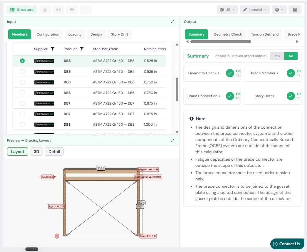

Engineer guide
Designing DonoBrace bracing to AISC 360
DonoBrace (Donovan Group Holdings Ltd, Whangarei, New Zealand; manufactured in the US by Behlen Mfg Co., Columbus, Nebraska) supplies a tension-only rod bracing system for steel framing. In the US it is recognized under ICC-ES ESR-5572, which publishes the nominal tensile strengths of the brace connectors for use with ANSI/AISC 360 and ANSI/AISC 341 under the IBC. SPEC Toolbox designs the brace and its bolted connection using those values, in LRFD or ASD.
Product range
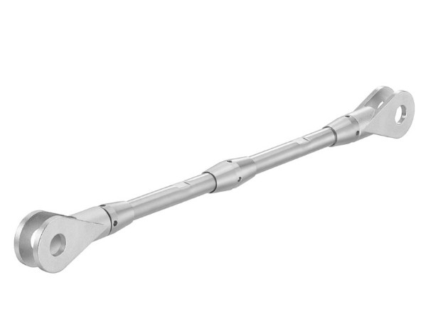
The integration covers the four DonoBrace sizes evaluated in ESR-5572. Each brace is a threaded bar, coupled at one end where required, with two-part end bracket plates that bolt to a gusset plate on the braced frame. Sizes
- DB5, DB6, DB7 and DB8, with actual bar diameters of 0.591, 0.690, 0.787 and 1.043 in. (15, 17.5, 20 and 26.5 mm) and gross areas of 0.274, 0.374, 0.486 and 0.854 sq in.
Components
- ASTM A722 Grade 150 threaded bar (rolled thread, so the effective net area equals the gross area), a coupler for brace lengths over about 19 ft, two-part end bracket plates in 1/4 to 1/2 in. ASTM A572 Gr. 50, anchor and fix nuts, lock and spring washers, and a stop washer on DB7 and DB8.
Connection to the gusset
- One ASTM F3125 Grade A325 bolt in double shear per end, from 3/4 to 1-1/4 in. diameter, hot-dip galvanized, with A563DH nut and F436 washer; the DonoBrace capacity tables also publish a PLUS connection using an A490 bolt with a thicker gusset plate.
Compatibility
At a glance, in the US scope the DonoBrace connectors support:
- Roof and wall bracing in Ordinary Concentrically Braced Frames (OCBF), resisting wind and seismic loads.
- Seismic Design Categories A through F.
- Tension only; no compression or buckling capacity is evaluated.
- LRFD or ASD.
- Compliance with the City of Los Angeles Building Code and the California Building Code, through the report’s supplements.
What's distinctive
- High-strength bar, with the strengths tabulated per size. The bar is ASTM A722 Grade 150 (Fy 120 ksi, Fu 150 ksi), and the report tabulates the nominal tensile yielding and rupture strengths directly: FyAg of 32.9, 44.9, 58.4 and 102.6 kips and FuAe of 41.1, 56.1, 73.0 and 128.2 kips for DB5 to DB8.
- Product-specific Ry and Rt for seismic design. Where AISC 341 applies, the report requires its own expected-strength ratios in place of the generic material values: Ry of 1.34, 1.22, 1.24 and 1.15 and Rt of 1.19, 1.10, 1.12 and 1.06 for DB5 to DB8, used for the brace-connection required strength.
- Rolled threads, so the net area is not reduced. The bar threads are rolled rather than machine cut, so the effective net area equals the gross area and the tensile rupture check is not penalised by a reduced section.
- A standard and a PLUS connection. The manufacturer’s connection tables give a standard connection with an A325 bolt and a thinner gusset plate, and a PLUS connection with an A490 bolt and a thicker plate, for seismic-dominated bracing where the connection must develop more of the brace strength.
- A stiffness reduction factor for drift. The system is supplied with per-size stiffness reduction factors (0.94, 0.90, 0.85 and 0.75 for DB5 to DB8) that account for the connection and coupler, so the brace axial stiffness used in a story-drift check reflects the installed assembly rather than the bare bar.
In the platform
The DonoBrace connectors are available in the SPEC Toolbox Bracing Design calculator, worked in LRFD or ASD to ANSI/AISC 360-22 and 341-22 with loads to ASCE/SEI 7-22:
- Members: the DonoBrace supplier and product (DB5 to DB8), steel bar grade, actual bar diameter, end bracket plate thickness, bolt grade (A325 or A490), whether the bolt threads are included in or excluded from the shear plane, gusset plate thickness and edge distance, and the bearing condition (deformation considered or not considered).
- Configuration and Loading: the braced bay geometry, story heights and applied story forces, with the framing members shown for visualization.
- Design and Story Drift: the design philosophy (LRFD or ASD) and the drift check.
The calculator reports a Geometry Check (the brace angle), the Tension Demand, the Brace Member and Brace Connection utilizations and the Story Drift, with a Layout, 3D and Detail preview of the bracing. The brace member result names the governing limit state and the connection result is reported at the Emh level with the overstrength factor applied, in imperial units. Consistent with the report, the design of the gusset plate and of the connection between the brace connector and the rest of the OCBF, and fatigue, are outside the scope of the calculator, and the brace is used in tension only.
Design codes
Design follows ANSI/AISC 360 and, where the brace forms part of the seismic force-resisting system, ANSI/AISC 341, under the IBC, with loads to ASCE/SEI 7. ICC-ES ESR-5572 tabulates nominal tensile strengths, FyAg for tensile yielding of the gross section (AISC 360-22 Equation D2-1) and FuAe for tensile rupture of the net section (Equation D2-2, with the effective net area equal to the gross area because the threads are rolled), which are converted to available strengths with the AISC 360 Section D2 factors: for LRFD a resistance factor of 0.90 on yielding and 0.75 on rupture, and for ASD a safety factor of 1.67 on yielding and 2.00 on rupture. On that basis the allowable (ASD) tensile strengths are 19.7, 26.9, 35.0 and 61.4 kips and the design (LRFD) tensile strengths are 29.6, 40.4, 52.5 and 92.3 kips for DB5 to DB8, with yielding governing every size. For OCBF in Seismic Design Categories D, E and F the brace connection is designed to develop the required strength of AISC 341 Section F1 using the product-specific Ry and Rt of the report. The bolted connection to the gusset is checked to AISC 360-22 Section J3: bolt shear using the nominal shear stress of Table J3.2, reduced where the threads are included in the shear plane; gusset plate bearing and tearout by Equations J3-6a to J3-6d, taken in the deformation-considered or deformation-not-considered form as selected; and an edge geometry validation against the minimum edge distance of Table J3.4. Installation follows the manufacturer’s published installation instructions and the report, the more stringent governing, and special inspection follows IBC Chapter 17 and AISC 341 Chapter J.
More from this partner
Other DonoBrace Integrations
Design With DonoBrace
How current is the DonoBrace data in SPEC Toolbox?
It is written against ICC-ES ESR-5572, issued January 2026 (subject to renewal January 2027), including its City of Los Angeles and California supplements. Values are re-checked against the report at its next reissue before the integrated data changes.
Which DonoBrace products are part of the integration?
The four brace connector sizes evaluated in ESR-5572 – DB5, DB6, DB7 and DB8 – in ASTM A722 Grade 150 threaded bar, with their end bracket plates, nuts, washers and coupler, and the A325 bolted connection to the gusset plate.
What can the bracing be used for?
Roof and wall bracing in Ordinary Concentrically Braced Frames, resisting wind and seismic loads in Seismic Design Categories A through F, in tension only. Compression, buckling and fatigue are outside the scope of the report.
Is the gusset plate designed in the calculator?
No. The design of the gusset plate, and of the connection between the brace connector and the other components of the OCBF, is outside the scope of ESR-5572 and of the calculator; it is designed and sealed by the registered design professional. The calculator does check the bolted connection to the gusset for bolt shear, bearing and tearout.
What is the difference between the standard and PLUS connection?
The standard connection uses an ASTM F3125 Grade A325 bolt with the tabulated gusset plate thickness and edge distance; the PLUS connection uses an A490 bolt with a thicker plate. Seismic-dominated bracing may require the PLUS connection so the connection can develop the required strength of the brace.
Which Ry and Rt values are used for seismic design?
The product-specific values of ESR-5572 Table 3, which the report requires in place of the generic material values where AISC 341 applies: Ry of 1.34, 1.22, 1.24 and 1.15 and Rt of 1.19, 1.10, 1.12 and 1.06 for DB5, DB6, DB7 and DB8.
Free, browser-based, no download. Design any certified connection into your real materials in seconds.
Start Designing For Free →Get your products in front of every engineer specifying on the platform — at the point of design.
Get Your Products Specified →