
Timber Screw Design for AS1720
Launch the free Screw Design Calculator below & verify your design in seconds!
The AS 1720.1 Screw Calculator is a professional engineering tool designed to determine the Design Capacity (𝜙 Nj) of fastener connections in accordance with AS 1720.1:2010. This tool streamlines the design of Coach Screws and Type 17 Screws in Sawn Timber, Glulam, LVL, and CLT.
Key Features:

Key Screw Design Module Capabilities
Overview of Structural Screw Connections
Self-tapping screws are widely used in modern timber engineering to transfer axial and shear forces between structural elements. These fasteners provide high load-bearing capacity, efficient installation, and flexible connection configurations for timber-to-timber and timber-to-steel joints.
The SPEC Toolbox Screw Design module allows engineers to evaluate screw connections in timber structures using manufacturer-specific fastener data and internationally recognized design standards. The calculator integrates real screw geometries and product libraries from leading suppliers, enabling accurate modelling of screw behaviour and load transfer.
The tool supports multiple timber materials and connection configurations used in modern timber construction.
Supported member materials include:
-
Softwood
-
Hardwood
-
Glulam (GLT)
-
Cross-Laminated Timber (CLT)
-
Laminated Veneer Lumber (LVL)
-
Plywood
-
Steel plates for timber-to-steel connections
This flexibility allows engineers to design screw connections for a wide range of structural timber systems.
Interactive Connection Model
To support intuitive connection configuration, the calculator provides an interactive 3D visualization of the screw arrangement and connected members.
The visualization displays:
-
screw orientation
-
load directions
-
member geometry
-
screw placement within the timber elements
Users can rotate and inspect the model to clearly understand the connection behaviour and load transfer mechanism before performing structural verification.
This visual feedback helps engineers confirm that the geometry and loading conditions correspond to the intended connection configuration.
Primary and Secondary Member Definition
The calculator allows engineers to define the structural members involved in the connection.
Two members can be configured:
-
Member 1 – primary structural element
-
Member 2 – secondary element or connected member
For each member, the following properties can be defined:
-
member material type
-
member dimensions
-
characteristic timber density (ρk)
-
mean density (ρmean)
The density values are used to calculate the embedment strength of the timber and therefore influence the resistance of the screw connection.
Additionally, the grain orientation relative to the screw can be defined to correctly represent load transfer behaviour in the timber.
Applied Forces
Screw connections may be subjected to axial and shear forces acting in multiple directions.
The calculator allows engineers to define the loads acting on the connection, including:
-
Fx – shear force in the x-direction
-
Fy – shear force in the y-direction
-
Fz – axial force acting along the screw axis
The combined shear force is automatically calculated based on the defined load components and used for connection verification.
The applied forces are visualized in the connection model, making it easier to understand how loads act on the fasteners and structural members.
Supplier and Product Library
The Screw Design module integrates fastener data from recognized manufacturers, allowing engineers to select screws directly from supplier libraries.
Users can define:
-
Screw supplier
-
Screw family
-
Specific screw type
Each screw type includes predefined product properties such as:
-
screw diameter
-
thread configuration
-
characteristic strength values
-
withdrawal resistance parameters
This integration ensures that connection calculations are based on realistic fastener properties and certified manufacturer data.
Screw Type and Thread Configuration
Different screw configurations can be selected depending on the connection requirements.
Available options include:
-
Partially threaded screws
-
Fully threaded screws
Thread configuration affects the load transfer mechanism and determines whether the screw primarily resists:
-
shear forces
-
axial forces
-
combined loading conditions
The calculator also supports smart screw length selection, helping engineers identify suitable fastener lengths based on connection geometry.
Supported Design Methods
Screw connections in the Australian design environment can be evaluated using several design approaches depending on the applicable standard and available fastener certification.
The calculator supports the following design methods:
-
EN 1995-1-1:2004 (Eurocode 5)
The European design standard for timber structures, widely used for timber connection design including screw fasteners. -
AS 1720:2010
The Australian Timber Structures Standard, which defines design provisions for timber connections including fasteners, load combinations, and resistance calculations. -
prEN 1995:2023
The upcoming revision of Eurocode 5, introducing updated calculation models and revised design rules for timber connections. -
EN 1995-1-1:2004 (Supplier ETA)
This method allows connection design using manufacturer-specific European Technical Assessment (ETA) data for proprietary screws. Resistance values are based on certified product performance. -
AS 1720:2010 (Supplier ETA)
This option combines the Australian timber design standard with manufacturer-verified fastener performance data, enabling design based on certified proprietary screw products.
These design methods allow engineers to perform connection verification using either general design code provisions or manufacturer-verified fastener performance data.
Screw Arrangement and Spacing
The geometric arrangement of screws significantly influences the resistance and failure modes of timber connections.
The calculator allows engineers to configure screw placement using two approaches.
Manual Arrangement
Engineers can manually define the screw layout, including:
-
number of screws
-
spacing between screws
-
edge distances
-
end distances
Minimum Distance and Spacing Rules
Alternatively, the calculator can automatically apply minimum spacing and edge distance requirements according to the selected design standard.
These geometric rules help prevent brittle timber failure modes such as splitting.
The following parameters are considered:
-
spacing parallel to grain
-
spacing perpendicular to grain
-
edge distances
-
end distances
-
fastener positioning relative to the member face
Connection Capacity Checks
After defining the screw configuration, timber properties, geometry, and applied loads, the calculator performs structural verification of the connection.
The output summary includes the following checks.
Geometry Check
Verifies that screw spacing, edge distances, and end distances satisfy minimum design requirements.
Shear Capacity
Evaluates the shear resistance of the screw connection based on timber embedment strength and fastener resistance.
Axial Capacity
Evaluates the axial resistance of the screw connection, including withdrawal resistance where applicable.
Combined Actions
When axial and shear forces act simultaneously, the calculator verifies the combined loading condition to ensure the connection capacity is not exceeded.
Slip Modulus
The calculator also provides the slip modulus of the screw connection, representing the stiffness of the fastener under load. This value is important for structural modelling and deformation analysis.
Tutorials
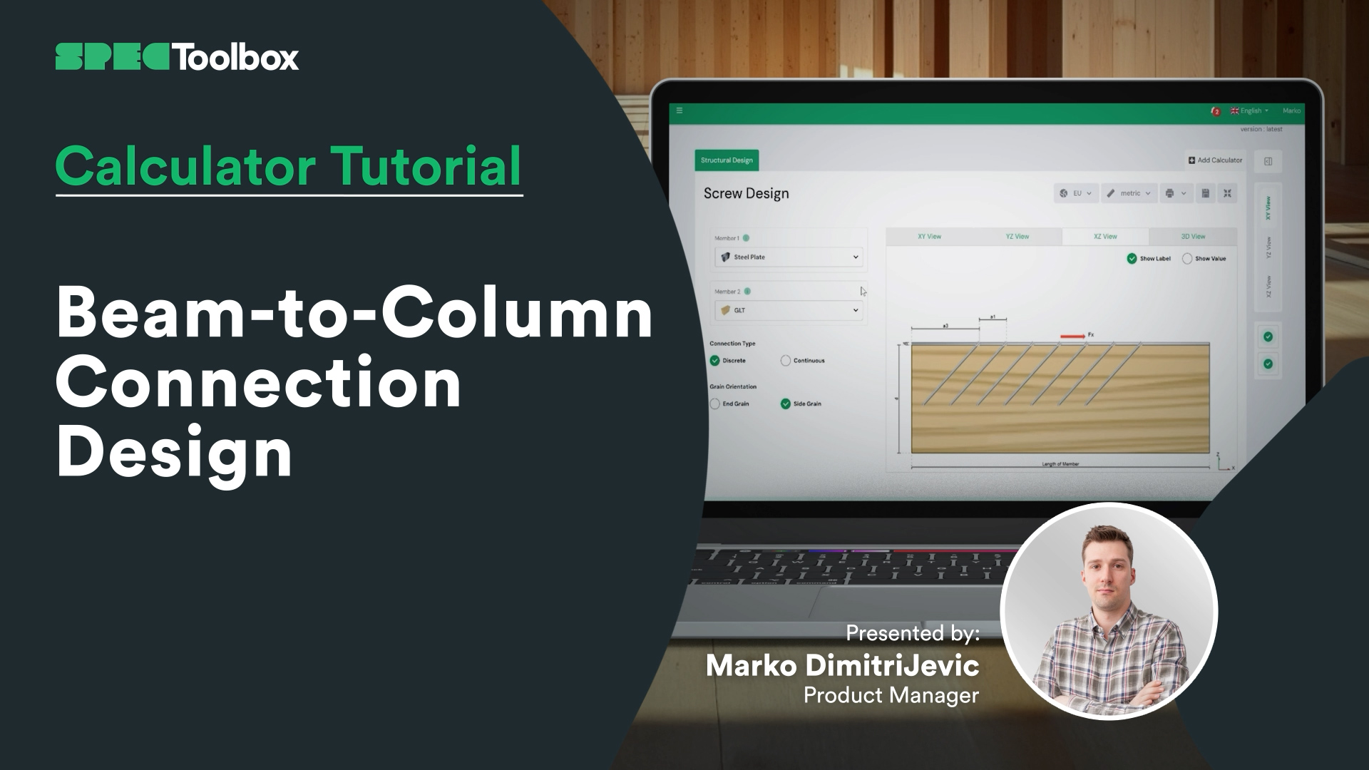
Beam-to-Column Connection Design
Beam-to-Column Connection Tackle the complexity of Beam-to-Column joints in this focused tutorial. We demonstrate how to replace complex bespoke steelwork with smart screw arrangements. Using the Screw Module, we verify the capacity of inclined screw groups to handle significant shear loads directly at the support interface.
Key Screw Benefits:
Crossed-Screw Configurations: Shows how arranging screws in crossed pairs (X-formation) significantly boosts stiffness.
Ductility & Safety: detailed look at how modern structural screws provide necessary ductility for safe, predictable failure modes.
CLT Floor-to-Wall Connection Design

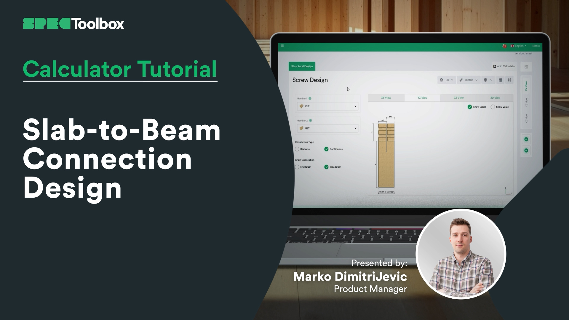
Slab-to-Beam Connection Design
Half-Lap Connection Design
Join us as we break down the Half-Lap joint design, focusing on maintaining structural continuity without external steel plates. Using the Screw Module, we walk through the auto-checking of edge distances and spacing requirements critical for these tight geometric joints.

Screws: Laterally loaded timber to timber end grain
We are thrilled to release the Laterally Loaded Timber-to-Timber End Grain Module, a powerful tool for engineers designing connections with screws subjected to lateral loads. This specialized calculator ensures accuracy and flexibility for timber connection designs.
Key Features:
• Design Codes: Supports three design codes for laterally loaded screws: EN 1995:2004, AS 1720:2010, and prEN 1995:2023.
• Supplier Input: Input screws from top suppliers like Rothoblass, Eurotec, Sihga, Spax, and Simpson’s Strong Tie.
• Manual Input: Allows manual entry of screw parameters, including dimensions and material properties.
• Flexible Calculations: Perform calculations based on the selected supplier’s ETA document or design code.
• Dynamic Diagrams: Interactive diagrams that update based on your input data, visualizing load paths and screw performance.
• Comprehensive Summaries: Detailed summaries with geometry checks and shear capacity utilization, providing reliable data for design decisions.
• End Grain Connections: Specifically designed to calculate timber connections with screws fixed on the end grain direction.
This specialized calculator helps engineers ensure strong, reliable, and accurate timber connections under lateral loads.

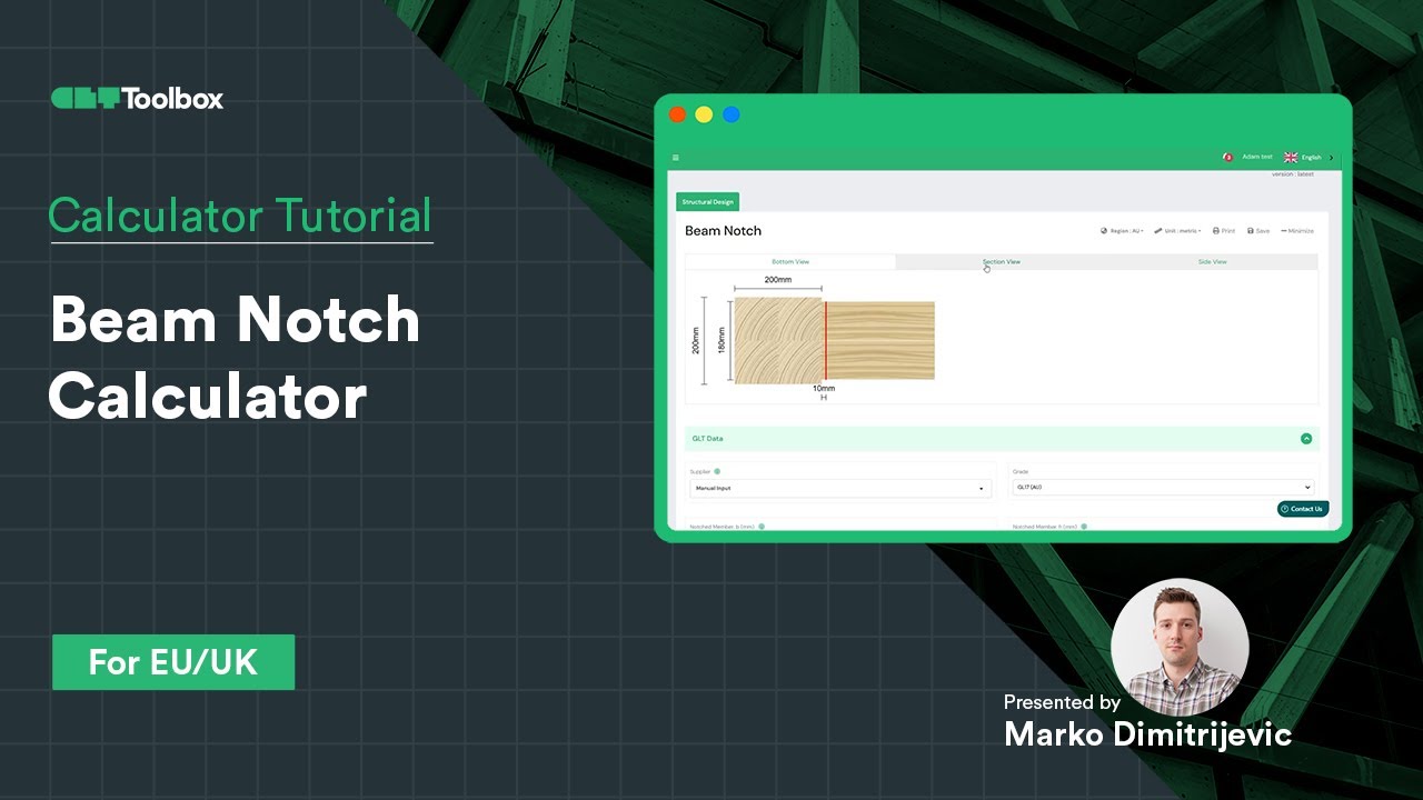
Beam Notch Calculator
Design & Verification of a GLT Beam Notch According to EC5 with CLT Toolbox
The key question: does the reduced cross-section provide enough capacity, or is reinforcement with screws required?
Here’s what we covered in this video:
– How to check notch capacity using EC5
– When and how to use reinforcement screws based on ETA data from suppliers
– Introduction to screw geometry inputs
– How screw position, orientation, and quantity can optimise the design
A practical guide to achieving safe and efficient timber connections. Would love to hear your thoughts or experiences with similar designs!
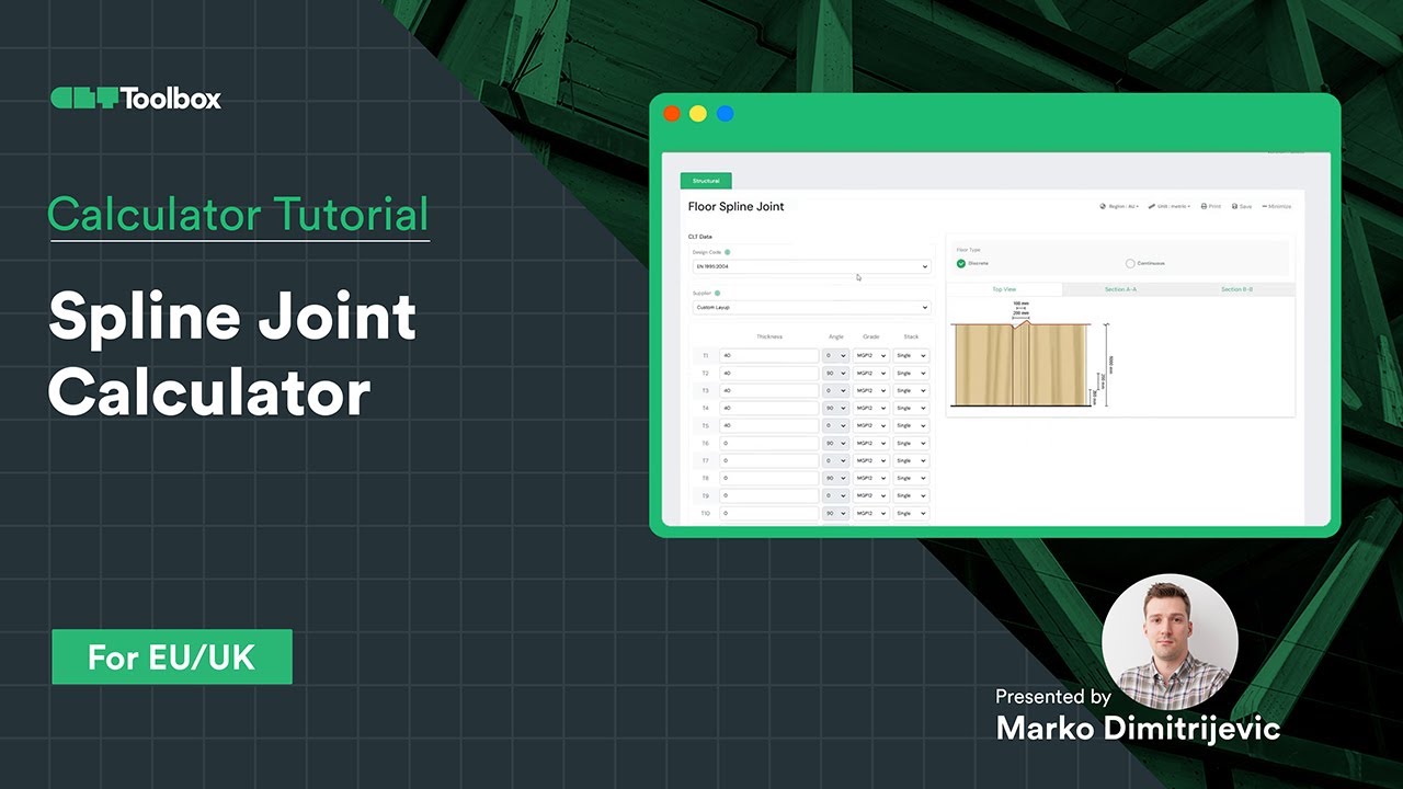
Spline Connection Calculator
Learn how to design a CLT spline panel-to-panel connection using input forces from diaphragm calculations. Selecting the CLT supplier, spline width, density and material, with an explanation of proper screw selection and availability for setting different screw suppliers, their screw families and screw types. For each group, there is educational content helping to select the right screw product. Easily switch between analytical methods, including the current and new Eurocode 5 approaches.


 Dowels
 CLT
CLT Screws
 GLT
GLT Brackets
 Light-frame
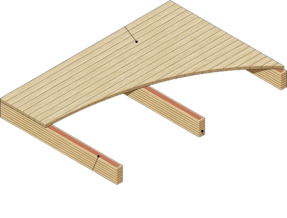 Ribbed Deck
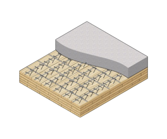 TCC
TCC