
 CSA S16:24 (Design of Steel Structures)
Design DonoBrace Bracing to CSA S16
SPEC Toolbox designs DonoBrace tension-only rod bracing to CSA S16:24 in limit states design, with loads to the National Building Code of Canada, using the manufacturer's published capacity tables. The integration covers the DB5, DB6, DB7 and DB8 brace connectors in ASTM A722 Grade 150 threaded bar, with factored tensile resistances of 131.5, 179.6, 233.8 and 410.2 kN, checking gross-section yielding and net-section fracture of the bar and the bolted connection to the gusset plate for bolt shear, bearing and tearout, in either a standard (A325) or PLUS (A490) configuration.
Start Designing for Free Back to DonoBrace CSA S16:24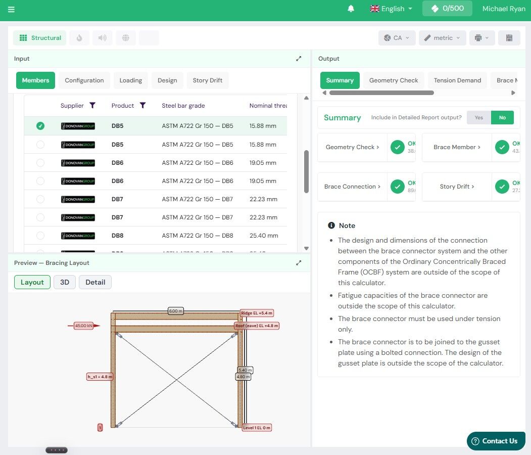


Engineer guide
Designing DonoBrace bracing to CSA S16
DonoBrace (Donovan Group Holdings Ltd) supplies a tension-only rod bracing system for steel framing. In Canada the product does not carry a Canadian evaluation listing; the manufacturer publishes capacity and connection tables calculated to CSA S16, and SPEC Toolbox designs the brace and its bolted connection from those values, in limit states design under the National Building Code of Canada.
Product range
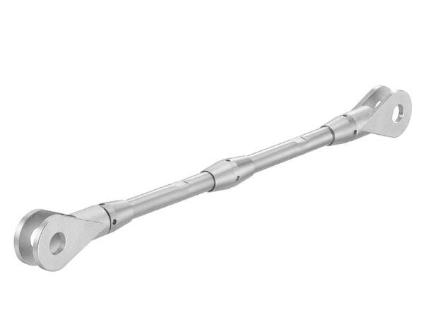
The integration covers the four DonoBrace sizes. Each brace is a threaded bar, coupled at one end where required, with two-part end bracket plates that bolt to a gusset plate on the braced frame. Sizes
- DB5, DB6, DB7 and DB8, with actual bar diameters of 15, 17.5, 20 and 26.5 mm and gross areas of 177, 241, 314 and 551 mm2.
Components
- ASTM A722 Grade 150 threaded bar (yield stress 827 MPa, tensile stress 1034 MPa), with rolled threads so the effective net area equals the gross area; a coupler for longer braces; two-part end bracket plates in ASTM A572 Gr. 50; anchor and fix nuts, lock and spring washers; and a stop washer on DB7 and DB8.
Connection to the gusset
- One bolt in double shear per end into a single ASTM A572 Gr. 50 gusset plate: an ASTM F3125 Grade A325 bolt in the standard connection, or an A490 bolt with a thicker plate in the PLUS connection, with the tabulated plate thickness and bolt edge distance for each size.
Compatibility
At a glance, in the Canadian scope the DonoBrace connectors support:
- Roof and wall bracing in concentrically braced steel frames, resisting wind and seismic loads.
- Tension only; no compression or buckling capacity is evaluated.
- Limit states design (LSD).
- A standard (A325) or PLUS (A490) bolted connection to the gusset plate, with the bolt threads either intercepting or excluded from the shear plane.
What's distinctive
- High-strength bar, with the resistance checked both ways. The bar is ASTM A722 Grade 150 (Fy 827 MPa, Fu 1034 MPa), and the calculator reports both limit states of CSA S16:24 Clause 13.2: gross-section yielding with a resistance factor of 0.90, and net-section fracture with a resistance factor of 0.75. Yielding governs, giving factored tensile resistances of 131.5, 179.6, 233.8 and 410.2 kN for DB5 to DB8.
- Rolled threads, so the net area is not reduced. The threads are rolled rather than machine cut, so the effective net area equals the gross area and the net-section fracture check is not penalised by a reduced section at the thread.
- A standard and a PLUS connection. The tables publish the gusset plate thickness and bolt edge distance for each size in both configurations, so the connection can be shown to develop the brace; seismic-dominated bracing may require the PLUS connection.
- A stiffness reduction factor for drift. The system carries per-size stiffness reduction factors (0.94, 0.90, 0.85 and 0.75 for DB5 to DB8) that account for the connection and coupler, so the brace axial stiffness used in the story-drift check reflects the installed assembly rather than the bare bar.
In the platform
The DonoBrace connectors are available in the SPEC Toolbox Bracing Design calculator, worked in limit states design to CSA S16:24 with loads to NBC 2025, in metric units:
- Members: the DonoBrace supplier and product (DB5 to DB8), steel bar grade, actual bar diameter, end bracket plate thickness, bolt grade (A325 or A490), whether the bolt threads are included in or excluded from the shear plane, gusset plate thickness and edge distance, and the bearing condition (deformation considered or not considered).
- Configuration and Loading: the braced bay geometry, story heights and applied story forces in kN, with the framing members shown for visualization.
- Design and Story Drift: the design code and philosophy, and the drift check.
The calculator reports a Geometry Check (the brace angle), the Tension Demand, the Brace Member and Brace Connection utilizations and the Story Drift, with a Layout, 3D and Detail preview of the bracing. Consistent with the manufacturer’s scope, the design of the gusset plate and of the connection between the brace connector and the other components of the braced frame is outside the scope of the calculator, fatigue is not covered, and the brace connector is used in tension only.
Design codes
Design follows CSA S16:24 (Design of Steel Structures) in limit states design, with loads to the National Building Code of Canada (NBC 2025). The brace member is checked to Clause 13.2: gross-section yielding, with the nominal strength Tn taken as Fy times the gross area and a resistance factor of 0.90, and net-section fracture, with Tn taken as Fu times the effective net area and a resistance factor of 0.75; because the threads are rolled, the effective net area equals the gross area. On that basis the factored tensile resistance of the brace is 131.5, 179.6, 233.8 and 410.2 kN for DB5 to DB8. The bolted connection to the gusset plate is checked to Clause 13: bolt shear in double shear to Clause 13.12.1.2, with the factored shear resistance taken as 0.60 times the resistance factor of 0.80 times the number of shear planes and the bolt area and tensile strength, reduced to 70 percent where the threads intercept a shear plane; gusset plate bearing to Clause 13.12.1.2(b); and gusset plate tearout to Clause 13.11, with an edge geometry validation on the bolt edge distance. The brace resists tension only; compression, buckling and fatigue are not evaluated, and the design of the gusset plate and of the connection to the rest of the frame rests with the registered design professional.
More from this partner
Other DonoBrace Integrations

Design With DonoBrace
How current is the DonoBrace data in SPEC Toolbox?
The Canadian design values are the manufacturer’s published capacity and connection tables, calculated to CSA S16 (revision 16). Values are re-checked against the tables at their next revision before the integrated data changes.
Does DonoBrace carry a Canadian evaluation listing?
No. There is no CCMC listing for this product. The Canadian design values in SPEC Toolbox come from the manufacturer’s published capacity and connection tables, calculated to CSA S16. The product’s third-party evaluation, ICC-ES ESR-5572, is a US report issued against the IBC and the AISC standards and does not cover Canada.
Which DonoBrace products are part of the integration?
The four brace connector sizes – DB5, DB6, DB7 and DB8 – in ASTM A722 Grade 150 threaded bar, with their end bracket plates, nuts, washers and coupler, and the bolted connection to the gusset plate in either the standard (A325) or PLUS (A490) configuration.
What can the bracing be used for?
Roof and wall bracing in concentrically braced steel frames, resisting wind and seismic loads, in tension only. Compression, buckling and fatigue are not evaluated.
Is the gusset plate designed in the calculator?
No. The design of the gusset plate, and of the connection between the brace connector and the other components of the braced frame, is outside the scope of the calculator and rests with the registered design professional. The calculator does check the bolted connection to the gusset for bolt shear, bearing and tearout, with an edge geometry validation.
What is the difference between the standard and PLUS connection?
The standard connection uses an ASTM F3125 Grade A325 bolt with the tabulated gusset plate thickness and bolt edge distance; the PLUS connection uses an A490 bolt with a thicker plate. Seismic-dominated bracing may require the PLUS connection so the connection can develop more of the brace resistance.
Free, browser-based, no download. Design any certified connection into your real materials in seconds.
Start Designing For Free →Get your products in front of every engineer specifying on the platform — at the point of design.
Get Your Products Specified →


