 Eurocode 5 (EN 1995-1-1)
Design Pitzl Brackets to Eurocode 5
SPEC Toolbox designs the Pitzl GePi face-fixed steel angle brackets to Eurocode 5 (EN 1995-1-1), using the characteristic load-carrying capacities of ETA-21/0750, a European Technical Assessment for three-dimensional nailing plates. The integration covers GePi 80, GePi 100 and GePi 240, each with and without the Sylodyn NC elastic interlayer, and the GePi PLANE flat plate, for timber to timber, timber to concrete and timber to steel connections in solid timber, glulam, CLT and LVL. Characteristic values are reduced to design values per EN 1995-1-1 2.4.3.
Start Designing for Free Back to Pitzl ETA-21/0750 — issued 2023-10-09 (replaces the 2021-08-21 issue); EAD 130186-00-0603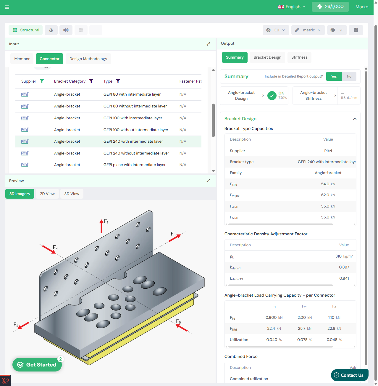
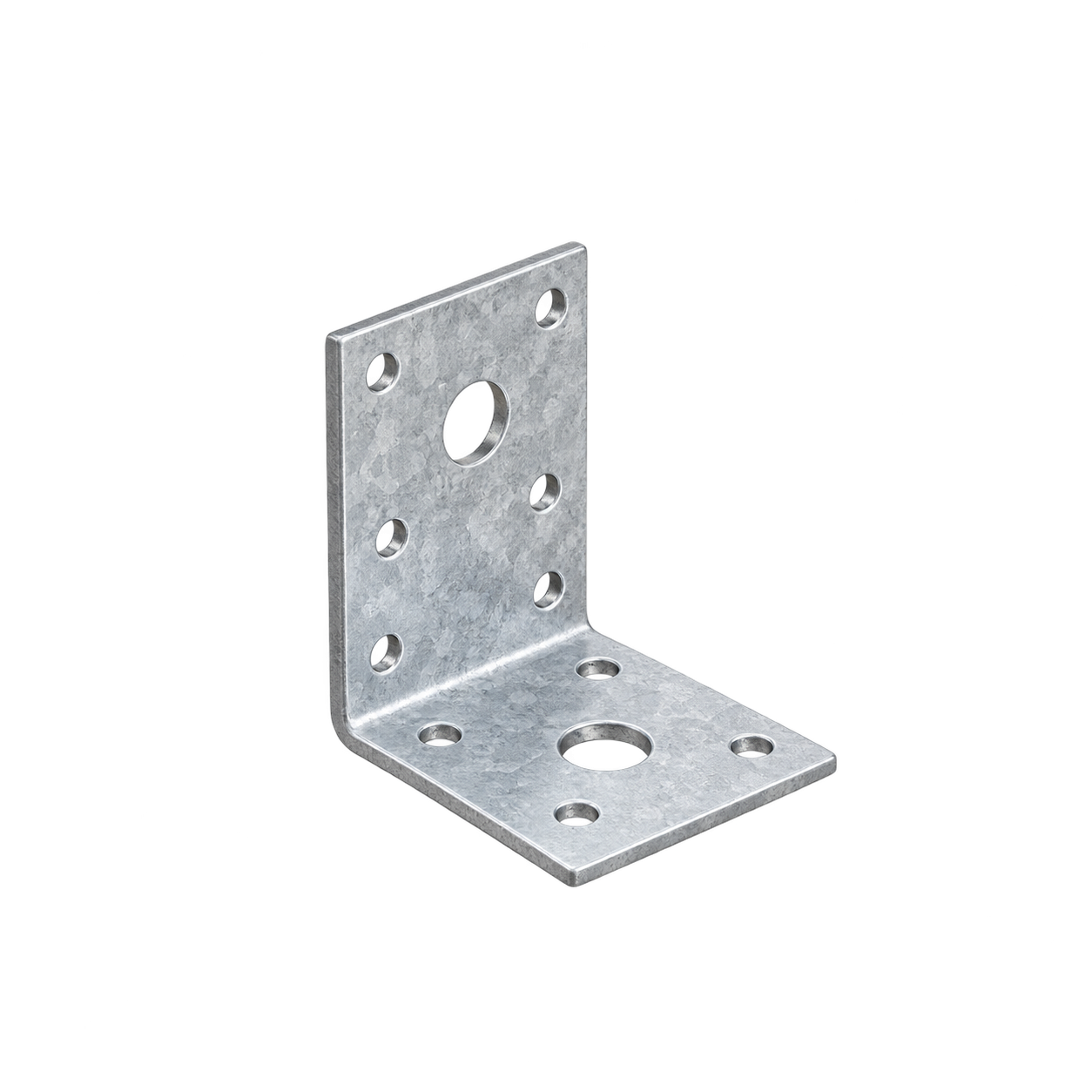

Pitzl Metallbau GmbH & Co. KG (Essenbach, Germany) manufactures the GePi range of one-piece, non-welded, face-fixed steel angle brackets for timber structures. The brackets are recognised under ETA-21/0750. SPEC Toolbox designs them to Eurocode 5 on the characteristic capacities of that assessment.
The integration follows the GePi range as assessed in ETA-21/0750, grouped by bracket type. The brackets are steel grade S250GD with a Z275 zinc coating, fixed to the timber with 8 mm self-tapping screws and to concrete or steel with metal anchors or concrete screws. Screw supporting plates are aluminium EN AW-6082 T6 or steel S235, as are the optional tension and shear plates.
Angle brackets
Flat plate connector
Supporting plates and accessories
At a glance, the Pitzl GePi brackets support:
The Pitzl GePi brackets are available in the bracket connection module and CLT Shear Wall calculator, worked to Eurocode 5:
Capacities are selected for the assigned strength class and density, the bracket configuration and the load direction, with the combined-force interaction applied where directions act together.
Design follows Eurocode 5 (EN 1995-1-1). ETA-21/0750 gives characteristic load-carrying capacities in the F1 (tension and uplift) direction and in the two orthogonal shear directions F2/F3 and F4/F5, together with mean connection slip moduli. The design capacity is the lesser of the timber-connection failure (screw withdrawal and embedment, with k_mod and the connection partial factor), the steel-plate failure with the steel partial factor, and, where the bracket is anchored to concrete, the anchor failure with its own partial factor. The tabulated values are tested capacities for the complete connection; the net cross-section at the screw holes, the minimum end and edge distances, the effect of a panel interlayer on the screw lateral capacity, and the anchor design are verified separately to Eurocode 5 and EN 1992-4.
It is written against ETA-21/0750, issued 2023-10-09, which replaces the issue of 2021-08-21 and is assessed against EAD 130186-00-0603 for three-dimensional nailing plates. Values are re-checked at the next reissue.
To the timber, with 8 mm self-tapping screws to ETA-19/0553 or others of equal or better properties to EN 14592. Minimum lengths run from 80 mm on the wall side to 160 mm on the slab side, with the count set per bracket and side. To concrete or steel, with 8 mm metal anchors or concrete screws.
The timber must be strength class C20 or better and free from wane under the bracket, and the connected parts must be in contact so that F1 compression transfers over the contact area. An elastic interlayer under permanent compression has to be at least 500 mm long, and a panel interlayer to 26 mm.
Free, browser-based, no download. Design any certified connection into your real materials in seconds.
Start Designing For Free →Get your products in front of every engineer specifying on the platform — at the point of design.
Get Your Products Specified →
Get the latest updates, tools, and resources for smarter timber design—straight to your inbox.

© 2026 SPEC Toolbox.
Website by Sanatan