
CLT shear walls are widely used as the primary lateral force-resisting system in European mass timber buildings. Their design is governed primarily by Eurocode 5, with seismic requirements addressed through Eurocode 8. Structural performance depends on panel geometry, connection layout, diaphragm interaction, and the nonlinear behavior of mechanical fasteners. Key design checks include lateral resistance, overturning, sliding, stiffness, and ductility, with connection design typically controlling system behavior. This post outlines the main additions to SPEC toolbox’s CLT Shear Wall Calculator and how they are applied to real world design scenarios.
SPEC Toolbox’s CLT Shear Wall Calculator additions:
The effect of wall support on the design
In order to determine the tensile and compressive force at the base of the shear wall panel, SPEC Toolbox provides users the option to select which of the academically reviewed methods to choose. Here we will provide a brief overview of the methods:
Method I (Casagrande et al. 2016):
Analyzes shear walls using rigid body rotation and static equilibrium, with the rotation point at the panel edge, focusing on internal force balance.

Where τ is a lever arm coefficient that represent a reduction in width that considers the distance from the panel edge to the hold-down. It is equal to 0.9.
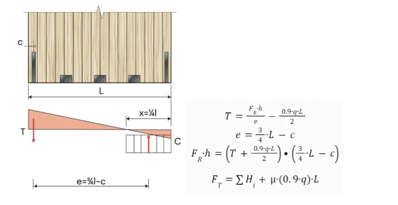
Method II (Wallner-Novak et al. 2014)
Uses a simplified rectangular stress block and accounts for frictional resistance, providing a more detailed approach to sliding resistance.

Method III (Tomasi 2014):
Similar to Wallner-Novak but the compression zone length is dependent on the compression strength and assumes an extremely stiff foundation with a refined neutral axis calculation.

Method IV (Pei et al. 2012):
Treats the CLT panel as a rigid body rotating around a corner with connectors modeled as elastic springs, relying on back-calibrated connection resistance and excluding sliding resistance from the analysis.

Method V (Reynolds et al. 2017):
A method similar to Method IV, featuring a triangular distribution of tensile capacity, but with the added consideration of a compression zone.


As you can see, methods III and V utilize a compression zone length in which the utilization of the compressive strength of the wall panel is at 100%. For these methods we use the compressive strength of the shear wall panel itself if the wall panel in question is supported by an infinitely stiff base, most likely a concrete foundation. This means that previously with these methods in the CLT shear wall calculator you could only design a shear wall panel at the ground level, which severely restricts the application of these methods.
That is why with the latest update of the CLT shear wall calculator we have added an option to specify if the support of the shear wall panel is timber (usually CLT) or a concrete foundation. If the user chooses the timber base option and methods III or V, instead of the compressive strength parallel to grain of the wall panel and the effective thickness of the wall panel, the calculation will use the perpendicular to grain compressive strength of the floor. Since the values of those two strengths differ greatly, this will cause a larger difference in the compressive zone length, lever arm length and tension in the hold down. The user can also manually specify the kc,90 factor used in compression perpendicular to grain verification.


With this update, a complete design of a multi storey CLT shear wall is possible with SPEC Toolbox.
Additional support connection method
We have added a sixth support connection method. This method was developed by Gavric and Popovski et al. in 2014.
It is similar to method IV (Pei et al. 2012) in that it features a triangular distribution of tensile forces between angle brackets and hold downs, but it also assumes a combined shear and tension action in the angle brackets. This is perfect for pairing with angle brackets with a high tensile and shear strength.

Angle bracket and hold down integration
In the previous version of the CLT shear wall calculator, users had to manually enter the capacity and stiffness of the hold downs and angle brackets.
With the new version of SPEC Toolbox’s CLT shear wall calculator users have the option to select hold downs and angle brackets from the list of various connector suppliers that are present on SPEC Toolbox’s platform. The calculator uses the stiffness and capacity values of the connectors from the suppliers’ ETA, so users don’t have to scour through supplier documentation to find these values as before.


 Anzor
Anzor ASH
ASH Binderholz
 Eurotec
 Hyne
Hyne KLH Supplier
 Klimas
 NeXTimber
 Pitzl
Pitzl Prolam
 Red Stag
 Rothoblaas
 Schmid Schrauben Hainfeld
 SIHGA
SIHGA Simpson Strong-Tie
 SPAX
SPAX Timber Unlimited
 Würth
Würth XLAM
XLAM XLAM Dolomiti
 Dowels
 CLT
CLT Screws
 GLT
GLT Brackets
 Light-frame
 Ribbed Deck
 TCC
TCC