Design Timber-Concrete Composite Floors
Design timber-concrete composite floors in Australia and New Zealand, combining a CLT panel with a concrete slab through real screw connector data rather than generic assumptions. Currently built on Eurocode 2 and Eurocode 5, since TCC has no dedicated AS 1720.1 provisions yet. Concrete, timber and connector capacity are checked together at both early and long-term stages, alongside deflection and vibration. Try the calculator to get started.
Start Designing for Free See Integrated Suppliers- EN 1992-1-1:2004, EN 1995-1-1:2004

About TCC
The New Standard for Australian Mass Timber Engineering
Timber–Concrete Composite (TCC) floor systems are gaining increasing attention as engineers seek solutions that combine the sustainability of timber with the stiffness and mass of concrete. By integrating a concrete slab with timber panels through mechanical connectors, TCC systems can significantly improve structural stiffness, vibration performance, and load-carrying capacity compared to timber-only floors.
Despite these advantages, designing timber–concrete composite floors remains complex. The structural behaviour depends on the interaction between timber, concrete, and the shear connectors that transfer forces between the two materials.
Under the Eurocode framework, TCC systems are typically designed using EN 1992-1-1 – Eurocode 2 (Concrete Structures) together with EN 1995-1-1 – Eurocode 5 (Timber Structures). Because composite timber–concrete floors are not covered by simplified “Deemed-to-Satisfy” provisions, engineers often rely on analytical approaches such as the Gamma Method or Extended Gamma Method to model partial composite action.
The engineer's guide
TCC, Eurocode 5
The Australian Engineering Platform for TCC Design
- Concrete, Timber and Connection Capacity Check: ULS Verification at t = 0 and t = ∞
- Vibration Check: Multiple vibration methods (Hamm et al. 2010, FP Innovations, prEN 1995:2023)
- Deflection Check: Deflection diagrams available for each load case.
- Screw Geometry Check: Screw spacing check.
- Connection Design Capacity Check: Withdrawal, Tensile Failure and Axial Capacity of Screws.
Overview of Timber–Concrete Composite Systems
TCC systems combine timber structural members with a concrete slab connected through mechanical fasteners, increasing stiffness, load capacity, and vibration performance vs. timber-only floors. Calculator models: CLT timber panels, reinforced concrete slab, inclined screw connectors. Evaluates: concrete capacity, timber capacity, connection capacity, composite bending behavior, deflection performance, vibration response.
Design Codes: EN 1992-1-1:2004 (Eurocode 2), EN 1995-1-1:2004 (Eurocode 5). Loading Code: EN 1991:2002 (Eurocode 1).
Geometry and Components
Two components: CLT timber panel (resists tensile stresses), concrete slab (resists compressive forces, increases bending stiffness). Geometry: CLT panel layup, concrete slab thickness, reinforcement parameters, connector spacing, span length.
CLT panel via manual layer input: layer thickness, fiber orientation, timber grade, stacking configuration. Concrete layer: concrete grade, concrete thickness, cement type, relative humidity. Reinforcement: reinforcement strength, bar diameter, reinforcement spacing (crack control and reinforcement verification).
Design Methods
- Extended Gamma Method
- Equivalent Gamma Method
Determine effective bending stiffness of composite section, considering slip between timber and concrete layers. Additional parameters: composite stiffness factor, verification condition (t=0 and t=∞), material design factors.
Loads
Users define span length, support conditions, load distribution. Analysis determines: bending stresses, shear forces, composite section stresses, connector shear forces.
Vibration Methods
- Hamm et al. 2010
- FPInnovations
- prEN1995:2023
Additional parameters: floor performance level, secondary width, damping ratio, walking frequency, floating screed stiffness, support condition.
Screw Data
Composite interaction achieved using inclined screw connectors. Manual input: screw type, tensile strength, associated density, nominal diameter, screw length, threaded length, inner thread diameter, tip length. Connection geometry: spacing along beam (a1), spacing across beam (a2), edge distance (a3), embedment length, connector position.
Design Checks
ULS (at t=0 and t=∞): Concrete capacity, Timber capacity, Connection design. SLS: Deflection, Vibration performance.
TCC, Eurocode 5
Why use timber–concrete composite floors?
Why are mechanical connectors critical in TCC design?
What’s News
Dive into our newest releases, articles, and tutorials designed to help you succeed.

CLT Floor-to-Wall Connection Design
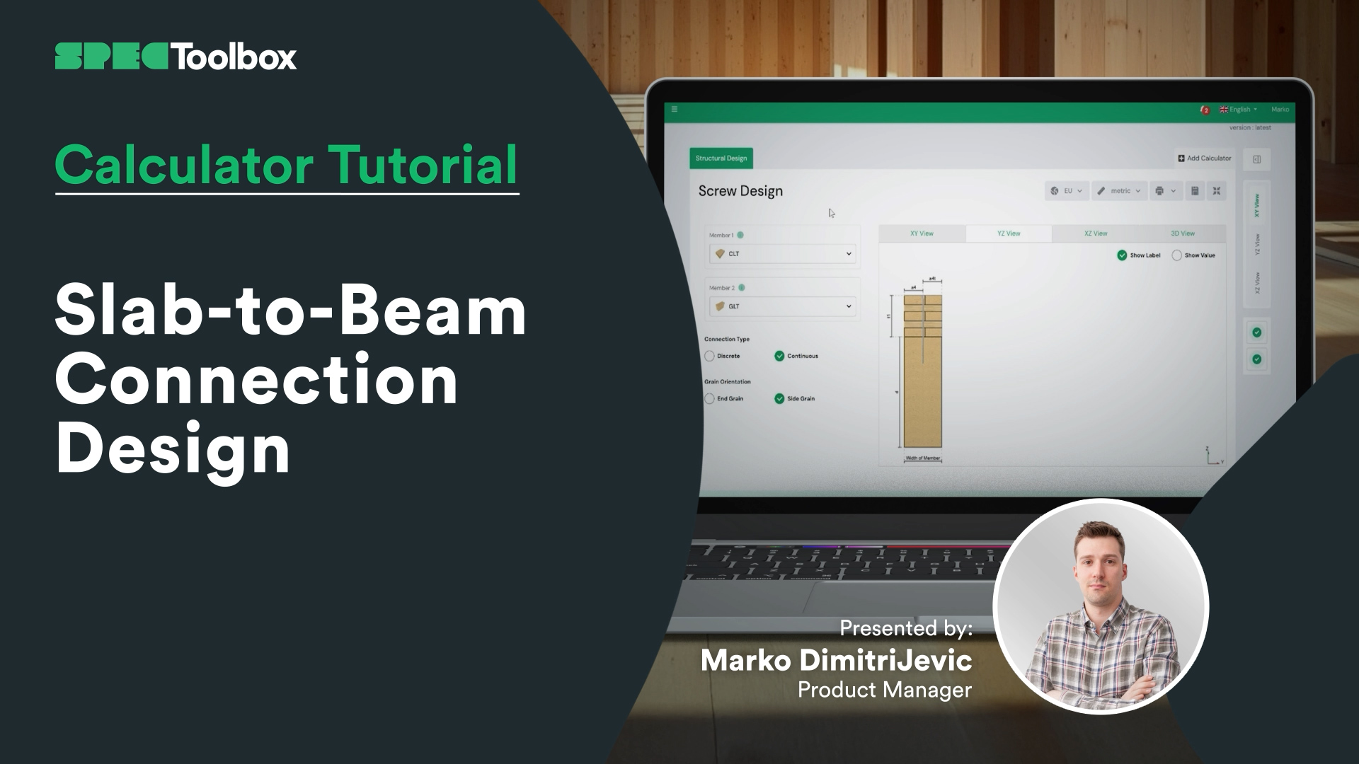
Slab-to-Beam Connection Design


CLT Diaphgram Design Calculator

CLT Diaphgram Design Calculator

CLT Floor Fire Design


CLT Floor Design Calculator
Gratis, browsergebaseerd, geen download. Ontwerp elke gecertificeerde verbinding in uw echte materialen in seconden.
Start gratis met ontwerpen →Breng uw producten onder de aandacht van elke ingenieur die op het platform specificeert – op het moment van ontwerp.
Laat uw producten specificeren →