Design CLT to AS 1720.1
A full set of CLT calculators for floor, fire, connections and shear wall design in Australia and New Zealand to AS 1720.1, with real product data from CLT and fastener suppliers built into every calculation, so you're specifying actual panel and connector performance, not assumptions. Move between local and imported product ranges without leaving the tool. Try the calculators to start specifying certified CLT solutions with confidence.
Start Designing for Free See Integrated Suppliers- AS 1720.1:2010 (Performance Solution basis) — connection/fire modules reference ÖNORM B EN 1995-1-2:2011 and prEN 1995-1-2:2023
- Austrian National Annex (ÖNORM B EN 1995-1-2:2011) used for fire

Partners
Integrated Suppliers
Every product below has live certified data wired into the calculators above — pick it from inside the tool.



About CLT Design
The New Standard for Australian Mass Timber Engineering
CLT Design in Australia is transforming the skyline, yet for many structural engineers, the path to a compliant mass timber design is filled with technical roadblocks. Despite its prevalence, specialized CLT design software for AS1720.1 is rarely taught at the university level, leaving a significant knowledge gap in the local industry.
Designing with the primary Australian timber code, AS1720.1, presents a unique challenge: the standard does not currently contain „Deemed-to-Satisfy“ (DtS) provisions for CLT. This forced reliance on a Performance Solution pathway requires engineers to use a verified CLT calculator to manually synthesize first principles with code-specific factors like k1, k4, and k6.
The engineer's guide
CLT Design, AS 1720.1
The Australian Engineering Platform for CLT Design
Our platform performs a comprehensive number of checks for CLT design to AS1720. The calculation modules include:
- CLT Floor Design: Incorporating vibration, deflection & strength according to AS 1720.1 capacity factors.
- Diaphragm Designs: According to the latest methods in Proholz design guides
- CLT Connections: Screw design to the latest methods in Eurocodes & AS1720.
- CLT Fire Design: With the latest methods coming from the New Eurocodes.
- Vibration (Serviceability): Assesses floor vibration performance using the most recent & advanced methods based on the latest Eurocodes.
Design of CLT Floors
Universal Supplier & Code Integration — Effective floor design begins with the CLT supplier. Our platform allows you to toggle seamlessly between local and international data: Australian Standards (automatically apply AS1720.1 modification factors such as k1, k4, and k6 for local products like XLam and NeXTimber); Eurocode Compliance (for European suppliers like KLH or Binderholz, the platform applies Eurocode 5 factors including kmod and γm, ensuring the right approach for imported CLT).
Analytical Methods for CLT Stiffness:
- The Gamma Method: Best for standard, uniform CLT panels with 3, 5, or 7 layers. It accounts for the rolling shear deformation in the cross-layers by using a simplified efficiency factor.
- The Extended Gamma Method: Our recommended method for thick panels (7-ply and above) or non-uniform layups. It provides a more refined calculation of effective stiffness by accounting for the rolling shear stiffness of every individual cross-layer, preventing overly conservative designs.
- The Shear Analogy Method: The most rigorous analytical approach, suitable for highly complex or asymmetric layups. It treats the panel as a composite beam with distinct bending and shear stiffness components, providing the highest level of accuracy for all layup configurations.
High-Performance Vibration Design — Vibration is often the governing serviceability limit state for CLT floors. We have included the latest Eurocode drafts to provide a superior design outcome: Support Conditions (model realistic scenarios including stiff or flexible supports to accurately predict floor behavior); Performance Levels (specify target performance levels to meet specific building requirements, moving beyond simple frequency checks to holistic occupant comfort).
This calculator goes beyond simple static deflection. The tool analyzes the Fundamental Frequency (f1) and Impulsive Velocity Response, allowing you to tune the floor mass and stiffness to meet strict vibration criteria (e.g., 8Hz for offices), ensuring the „feel“ of the floor matches the quality of the building.
Design of CLT Fire
Advanced CLT Fire Engineering — Structural fire design for mass timber is a critical component of any NCC 2025 Performance Solution. SPEC Toolbox simplifies this complexity by offering multiple verification pathways aiding engineering judgement, ranging from the widely adopted ÖNORM B EN 1995-1-2:2011 (Austrian National Annex) to the cutting-edge prEN1995-1-2:2023 (2nd Generation Eurocode). Whether you are utilizing a standard fire curve or a physically based fire model, the platform calculates precise charring depths and residual load-bearing capacities, helping your CLT panels meet stringent safety and integrity requirements.
Precision Charring & Bond-Line Integrity — Our engine accounts for the sophisticated physics of timber charring, moving beyond simple uniform rates. You can define the basic charring rate based on timber density and moisture content, and the platform automatically applies relevant ki factors to determine notional rates. Crucially, our 2nd Generation Eurocode module explicitly models bond-line integrity and gap effects, preventing the catastrophic loss of protection often ignored in simplified calculations.
Automated Factor Analysis for Performance Solutions — To provide total engineering transparency, SPEC Toolbox enables granular control over charring variables. The platform automates the calculation of Char Factors, including the GAP coefficient and specific k2, k3, and kg values required for layered protection systems. This „No Black Box“ approach allows engineers to either use code-specific defaults or bypass them with manual inputs from manufacturer fire tests, creating a verified path from first principles to project certification.
Design of CLT Connections
- Moving Beyond AS1720.1 Limitations— While AS1720.1 is the current Australianstandard, it is widely recognized as having limitations regarding modern mass timber connections. Advanced Yield Modeling (SPEC Toolbox utilizes the latest Eurocode methodologies, including the Johansen Yield Models, to provide more accurate and appropriate design outcomes than simplified local methods); ETA Integration (we integrate supplier-specific European Technical Assessments (ETAs), ensuring your designs utilize ultimate performance data unique to specific product families).
- Simplified Screw & Joint Design— Our platform transforms complex connection math into a streamlined, high-speed workflow: Preconfigured Joint Types (rapidly design and verify Half Laps, Splines, and Butt Joints with automated geometry checks); Steel-to-CLT (specialized modules for timber-to-steel connections, handling the complex stress distributions at the interface).
- The „Global-Local“ Connection Library— SPEC Toolbox is the only platform that allows you to pair your choice of CLT Supplier with the world’s leading Connection Manufacturers: Universal Fastener Selection (choose from top-tier brands includingRothoblaas, Spax, Eurotec, Sihga, Klimas, Simpson Strong-Tie, or Anzor); Verified Compatibility (seamlessly verify these fasteners against local and European panels like XLam, NeXTimber, or Red Stag).
Design of CLT Shear Walls
In-plane CLT Design (ProHolz vol 1 Clause 5.8) — ProHolz identifies three failure mechanisms for CLT shear walls: Mechanism 1 (Shearing of failure of the boards along a joint), Mechanism 2 (Shearing failure of the glued surface at the intersection of joints), Mechanism 3 (Shearing failure of the entire plate).
FP Innovation Clause 3.8 — By considering the shear stresses in the lamellas and the crossing areas, three different failure modes exist in CLT beams subjected to shear stresses: Failure Mode I (shear failure parallel to the grain in the gross cross-section), Failure Mode II (shear failure perpendicular to the grain in the net cross-section), Failure Mode III (shear failure in crossing area of orthogonal lamination).
Wall Connection Models — five load-transfer methods summarized: Method I (Casagrande et al. 2016) — rigid body rotation and static equilibrium, rotation point at panel edge. Method II (Wallner-Novak et al. 2014) — simplified rectangular stress block, accounts for frictional resistance. Method III (Tomasi, 2014) — similar to Wallner-Novak but different compression zone length, assumes extremely stiff foundation. Method IV (Pei et al. 2012) — treats CLT panel as rigid body rotating around a corner, connectors as elastic springs, excludes sliding resistance. Method V (Reynolds et al. 2017) — enhances triangular tensile distribution method, includes compression zone and friction for sliding resistance.
CLT Design, AS 1720.1
What is the best method to calculate the stiffness for CLT?
Does this platform enable "Deemed-to-Satisfy" (DtS) engineering?
What’s News
Dive into our newest releases, articles, and tutorials designed to help you succeed.

CLT Floor-to-Wall Connection Design
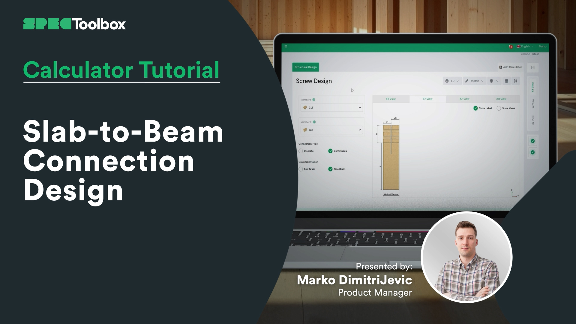
Slab-to-Beam Connection Design


CLT Diaphgram Design Calculator

CLT Floor Fire Design


CLT Floor Design Calculator
Kostenlos, browserbasiert, kein Download. Planen Sie jede zertifizierte Verbindung mit Ihren realen Materialien in Sekundenschnelle.
Kostenlos mit der Bemessung beginnen →Präsentieren Sie Ihre Produkte jedem Ingenieur, der auf der Plattform spezifiziert – direkt im Planungsprozess.
Lassen Sie Ihre Produkte spezifizieren →