
Designing screwed timber connections is a critical aspect of modern timber construction, where screws are increasingly used for their efficiency, speed of installation, and structural performance. With the growing adoption of mass timber and prefabricated wood products, engineers and builders rely on screwed connections to transfer loads and ensure structural integrity. However, the design of these connections requires careful consideration of factors such as screw type, embedment depth, spacing, and load orientation, all governed by the National Design Specification (NDS) for Wood Construction. This blog post will explore the key principles and best practices for designing screwed timber connections in the USA, including screw selection, capacity calculations, and detailing for optimal performance.
Choosing the right type of screw
Choosing the right timber screw is a pivotal decision in ensuring the structural integrity and durability of a timber connection. With a plethora of screw types, diameters, lengths, and coatings available, engineers and builders must carefully consider factors such as the specific timber species, connection geometry, load orientation, and environmental exposure.
Key things to consider when choosing the right screw are the type of connection (timber-to-timber or steel-to-timber) and type of loading (lateral or withdrawal). Partially threaded screws are better suited for timber-to-timber and steel-to-timber connections subject to lateral loads, while fully threaded screws are suited for timber-to-timber connections in which higher axial capacities are needed. Fully threaded screws are also used to reinforce timber beams for compression and tension perpendicular to grain (beam notches and holes, radial tension in curved beams). Head type also plays a significant role in timber-to-timber connections with partially threaded screws if higher axial capacity is needed, with flange head (washer-style) and hex head screws providing the highest head pull-through capacities.
 Fully threaded screwPartially threaded screw
HEAD TYPES
 Countersunk
 Double Countersunk
 Double Countersunk with ribs
 Shallow Pan Countersunk
 Wafer/Flange/Pancake
 Pan/Round
 Hexagon
 Bugle
Bugle Socket Button
 Socket Cap
Another crucial thing to consider is what type of timber is used in the connection. Not all screws are intended for use on hardwood and use of hardwood also requires pre-drilling.
To insure the required longevity of the building without costly retrofits, adequate corrosion protection of screws must be spec’d out.
Low Protection (Basic Indoor/Dry Use)
- Black Phosphate/Oxide: Very low resistance, for indoor projects only where moisture isn’t a concern.
- Zinc-Plated (Electroplated): Thin coating, good for interior wood, but chips easily outdoors, exposing steel to rust.
Moderate Protection (General Outdoor/Budget)
- Hot-Dipped Galvanized (HDG): Thicker zinc layer, sacrificial protection for steel; good for general outdoor use, but can fail if coating is scratched or in aggressive treated wood.
- Ceramic/Polymer Coatings (e.g., C3, C4, C5): Advanced coatings offering enhanced resistance to moisture and chemicals, often better than HDG for treated lumber.
High Protection (Treated Wood/Harsh Environments)
- A2 Stainless Steel (AISI 304): Excellent balance for most outdoor uses, sheds, garden furniture; resists acidic woods.
- A4 Stainless Steel (AISI 316): Marine-grade, best for coastal, pool areas, or very aggressive treated timbers (T5) with high salt/pollutant exposure.
Best Protection (Extreme/Marine/Chemical)
- HCR Stainless Steel: Offers the highest resistance for extreme conditions, like indoor pools or heavily polluted industrial settings.
Determining connection capacity
In the USA, the National Design Specification (NDS) for Wood Construction provides the primary framework for designing screw connections, offering guidance on calculating withdrawal, shear, and head pull-through capacities. Additionally, many modern screw products are evaluated and listed in ICC-ES Evaluation Reports (ICC-ESR), which provide specific design values and installation requirements for proprietary screws.
Most of the proprietary screws used in timber construction today are self-tapping screws. Design provisions and design values in the NDS are applicable to lag screws conforming to ANSI/ASME Standard B18.2.1 and wood screws conforming to ANSI/ASME Standard B18.6.1.
For self-tapping screws with dimensions similar to those provided in ANSI/ASME B18.2.1 (lag screws) or ANSI/ASME B18.6.1 (wood screws), the general form of the yield equations should apply for determining lateral design values. Accordingly, tabulated design values would also apply provided that the self-tapping screw dimensions meet or exceed the dimensions ASME B18.2.1 or ANSI/ASME B18.6.1 and the bending yield strength equals or exceeds the assumed bending yield strength in the table footnotes. In order to use lateral design provisions of the NDS, it must be assumed that fabrication and assembly of connections using self-tapping screws permits the development of the full bearing strength of the wood beneath the lag screw or permits yielding of the lag screw (i.e. installation does not damage the wood member or connection).
The lateral capacity of screws can be calculated using the yielding failure mode calculations presented in table 12.3.1A
- Failure mode Im (bearing in main member):


- Failure mode Is (bearing in side member):


- Failure mode II (fastener rotation without bending):


- Failure mode IIIm (development of plastic hinge in the fastener in main member):


- Failure mode IIIs (development of plastic hinge in the fastener in side member):


- Failure mode IV (development of plastic hinge in the fastener in both members):


NDS provides equations to calculate withdrawal capacity of the threaded part of the fastener and head pull-through capacity. The tensile capacity of the connection is the minimum of these values.
Withdrawal capacity of lag screws:
![]()
Withdrawal capacity of wood screws:

Head pull-through capacity:

Engineers using NDS equations for calculating withdrawal and head pull-through should be aware that these formulas don’t accurately represent the axial capacity of self-tapping screws, but should be regarded more as an estimation or a base point. Lag screws and wood screws as defined in the NDS require lead holes, where self-tapping screws don’t require them. There are also differences in thread geometries, root diameters, and hardness between self-tapping screws and wood or lag screws.
Because of the stated differences between self-tapping screws and lag or wood screws, it is much more accurate to use the tested withdrawal and pull-through capacities as listed in the appropriate ICC-ESR. Using accurate tested values will result in a safer connection, because, unlike yielding of the fastener, withdrawal and pull-through of the fastener are brittle failures and will cause a sudden collapse.
Whether NDS or ESR is used to determine the strength of the fastener, these strengths should be multiplied by all the necessary factors as presented in the table 11.3.1 of the NDS
Brittle failures should be avoided at all cost and that is why for screwed connections subject to lateral loading, besides determining yielding failure modes, it is crucial to check the timber members themselves for brittle failure. This is done by performing calculations presented in Appendix E of the NDS
Brittle failures that have to be checked are:
Net section tension capacity:

Row tear-out capacity:


Group tear-out capacity:


All of the previously stated calculations (fastener yielding failure modes according to NDS, ICC-ESR tested strengths, withdrawal and head pull-through according to NDS and ICC-ESR, brittle failures of timber members) are performed when designing screw connections with Spectoolbox’s Screw module.
Detailing the connection
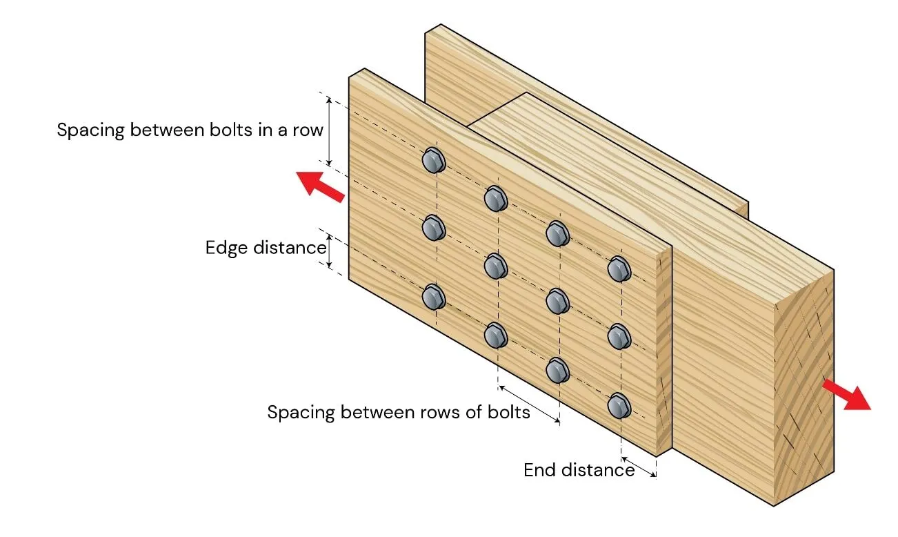
After selecting the applicable screw and determining the needed number of fasteners in a particular connection, the next step is detailing. In order to detail a safe connection, spacing and edge and end distances larger than the minimum allowed need to be called out. Both the NDS and fastener ICC-ESRs have prescribed minimum spacings and edge/end distances.
If NDS has been used to determine the strength of the fastener then minimum spacings and distances from the NDS should be used. If tested strengths from the ICC-ESR have been used to determine the strength of the fastener then minimum spacings and distances from the ICC-ESR should be used.
NDS has specified end distances in table 12.5.1A, spacing of fasteners in a row in table 12.5.1B, edge distances in table 12.5.1C and spacing between rows of fasteners in table 12.5.1D and maximum distance of outer most fasteners in Glulam members in table 12.5.1F
A particular property of the NDS defined spacings is that NDS regards a “row” of fasteners as those fasteners which are parallel to the direction of the force. This makes navigating all the spacing requirements difficult when a connection is subject to lateral loads in two directions.


For this reason, many engineers find it easier to use the minimum spacings and end/edge distances presented in appropriate ESRs. The distances and spacings are presented in parallel or perpendicular to grain direction for loading parallel to grain, perpendicular to grain and axial loading.
Whether NDS or ESR requirements are used, it is imperative to satisfy the requirements for minimum spacing and distances in order ro prevent premature, brittle failure of the connection.
Engineers using Spectoolbox’s Screw Module will have the option to select whether they want to use NDS or ESR strength values and depending on the selection, the appropriate spacing and distance requirements are used.


 Anzor
Anzor ASH
ASH Binderholz
 Eurotec
 Hyne
Hyne KLH Supplier
 Klimas
 NeXTimber
 Pitzl
Pitzl Prolam
 Red Stag
 Rothoblaas
 Schmid Schrauben Hainfeld
 SIHGA
SIHGA Simpson Strong-Tie
 SPAX
SPAX Timber Unlimited
 Würth
Würth XLAM
XLAM XLAM Dolomiti
 Dowels
 CLT
CLT Screws
 GLT
GLT Brackets
 Light-frame
 Ribbed Deck
 TCC
TCC