
Timber Stud Wall Design for AS1720
Design timber wall studs to AS 1720.1. Go beyond the limits of AS 1684 and engineer tall walls, jamb studs, and high-wind framing using MGP10, MGP12, and choosing your grades!
When the Tables Aren't Enough
For standard houses, AS 1684 (Residential Timber Framed Construction) is the bible. But modern architecture—with high ceilings, large window openings, and extreme wind categories—often pushes framing beyond the scope of the standard tables.
The SPEC Toolbox Stud Wall Calculator performs a first-principles engineering analysis to AS 1720.1. It allows you to verify studs for specific heights (e.g., 3.6m), localized wind pressures, and heavy point loads that simplified span tables simply cannot handle.
What This Calculator Does
This tool analyzes a vertical timber stud as a structural Beam-Column under combined Gravity (Roof/Floor) and Lateral (Wind) loads. It verifies:

Key Stud Design Capabilities
Overview of Light-Frame Timber Stud Design
Light-frame timber construction is one of the most widely used structural systems for residential and low-rise buildings. In this system, vertical timber members known as studs transfer loads from floors and roofs down to the foundation while being stabilized by horizontal members and structural sheathing.
SPEC Toolbox provides a dedicated Stud Design calculator that allows engineers to analyze the structural performance of timber studs within light-frame walls. The calculator evaluates axial compression, bending effects, buckling behavior, and stability conditions according to Australian timber design provisions.
The tool supports solid timber studs used in light-frame wall assemblies, allowing engineers to define geometric properties, spacing, loading conditions, and structural parameters to verify member performance under combined loads.
For the Australian region, the calculator supports the following timber design standards:
• AS 1720:2010 – Timber Structures
• NZS AS 1720:2022 – Timber Structures (New Zealand/Australian adaptation)
• EN 1995-1-1:2004 (Eurocode 5)
These standards define the design procedures for timber members under axial compression and bending, including stability checks and load combinations.
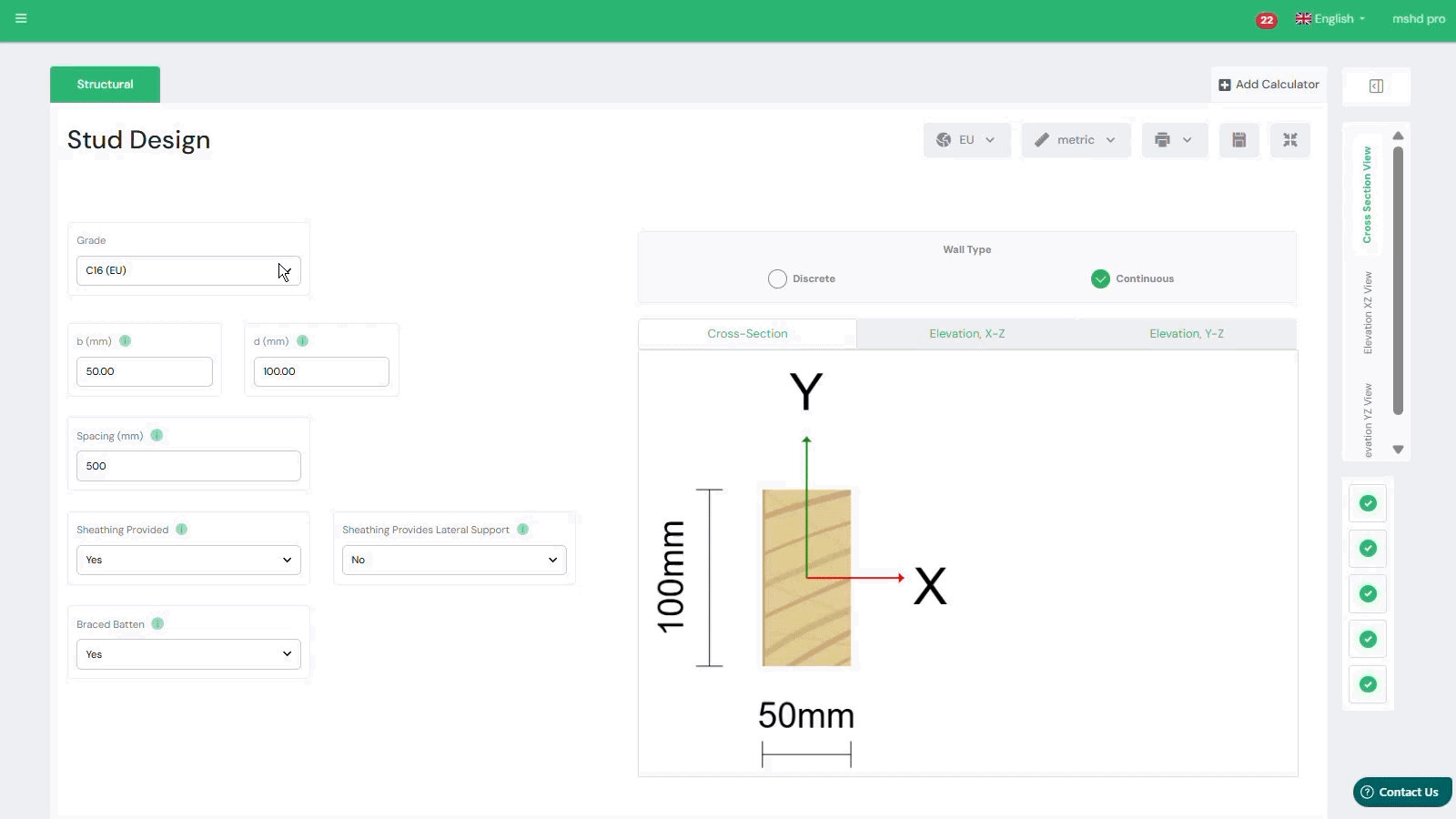
Timber Stud Properties
The structural capacity of a light-frame wall depends primarily on the geometry and material properties of the timber studs.
The calculator allows engineers to define the following parameters:
-
Timber grade
-
Stud width (b)
-
Stud depth (d)
-
Stud spacing
These parameters determine the cross-sectional resistance and slenderness of the stud.
Stud spacing is particularly important because it determines the tributary load area transferred from floors and roofs to each individual stud.
Wall Type
The wall assembly may be defined as:
• Discrete wall
• Continuous wall
A continuous wall configuration assumes that studs act as part of a continuous wall system with load redistribution between members. A discrete configuration treats each stud as an independent structural element.
Sheathing and Bracing Conditions
Sheathing materials such as plywood, OSB, or structural boards can significantly influence the stability and buckling behavior of the studs.
The calculator allows engineers to define:
-
Whether sheathing is present
-
Whether sheathing provides lateral support
-
Whether braced battens are installed
These parameters influence the effective buckling length and lateral stability of the stud.
Timber Design Standards
The calculator allows engineers to perform stud design according to several timber design codes.
The following design standards are available:
-
AS 1720:2010 – Timber Structures
-
NZS AS 1720:2022 – Timber Structures
-
EN 1995-1-1:2004 – Eurocode 5
Each standard provides different design procedures and safety factors for timber compression members.
The selected design standard determines the applicable material factors, load combinations, and stability verification procedures used in the calculation.
Load Cases and Combinations
The structural behavior of light-frame studs is governed by the loads acting on the wall system. The calculator allows engineers to define the primary load components transferred to the studs.
The following load types can be considered:
• Permanent loads (G)
• Imposed loads (Q)
• Wind loads (W)
• Snow loads (S)
These loads are combined according to the load combination rules defined by the selected loading standard.
Loading Code
Load combinations are defined using the following loading standard:
• AS/NZS 1170.0:2002 – Structural Design Actions
This standard defines the general principles for combining permanent, imposed, wind, and snow loads in structural design.
The loading code is automatically applied depending on the selected timber design standard.
Load Combination Settings
The calculator allows engineers to define:
-
Load combinations
-
Loading code
-
Combination factors
These parameters determine how loads are combined when evaluating the structural capacity of the stud.
Combination factors such as ψ-factors are applied to account for the probability of simultaneous occurrence of variable loads.
Axial Loads
Vertical loads transferred from floors or roof systems act as axial compression forces on the studs.
The calculator allows engineers to define distributed loads acting along the wall:
-
Permanent load (gk)
-
Imposed load (qk)
-
Wind load (wk)
-
Snow load (s)
These loads represent the tributary load carried by each stud.
Lateral Loads
Wind acting on the wall produces lateral pressure that generates bending in the studs.
The calculator allows engineers to define lateral loading values which are used to calculate:
-
bending stresses
-
combined bending and compression effects
These loads are combined with axial loads during structural verification.
Automated Stud Capacity Checks
After defining the geometry, material properties, and loads, the calculator performs a complete structural verification of the stud.
The following checks are automatically evaluated:
Bending Design
Verifies that the stud has sufficient bending capacity under lateral loads.
Compression Check
Evaluates the axial compression resistance of the stud.
Strength Interaction Check
Ensures that combined axial and bending stresses remain within allowable limits.
Buckling Verification
Checks the global buckling resistance of the stud under axial compression.
Lateral Torsional Stability
Evaluates the resistance of the stud against lateral torsional instability caused by bending and compression.
Tutorials
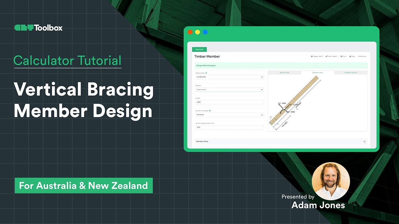
Vertical Bracing Member Design
Learn how to use the CLT Toolbox Member Calculator to design a vertical bracing diagonal. We’ll walk you through importing analysis results from external tools, identifying maximum tension and compression forces, and selecting the right inputs—grades, sections, code specifics, and forces. Plus, we’ll break down the results, covering material properties and all key design checks. CLT Toolbox is here to be your partner in designing timber projects!
Frequently Asked Questions
Is this compliant with NCC?
Yes. While AS 1684 is a “Deemed-to-Satisfy” manual, a design to AS 1720.1 (which this tool produces) is a primary reference standard in the NCC and is fully accepted for certification.

 Dowels
 CLT
CLT Screws
 GLT
GLT Brackets
 Light-frame
 Ribbed Deck
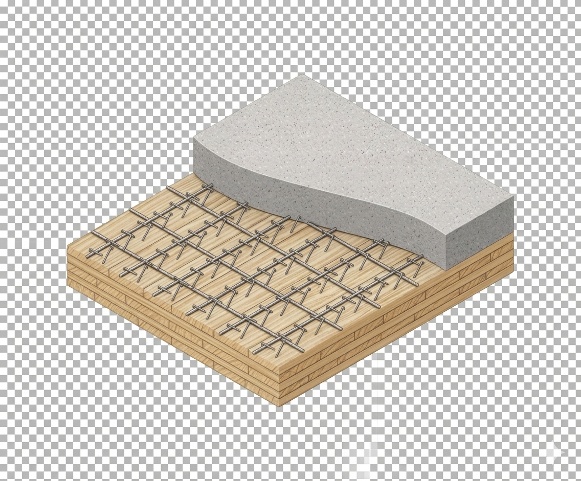 TCC
TCC