
Timber Concrete Composite (TCC) Design Software for AS1720.1 | Engineering Platform
Launch the free Timber Concrete Composite (TCC) Calculator below & verify your design in seconds!
The New Standard for Australian Mass Timber Engineering
Timber–Concrete Composite (TCC) floor systems are gaining increasing attention as engineers seek solutions that combine the sustainability of timber with the stiffness and mass of concrete. By integrating a concrete slab with timber panels through mechanical connectors, TCC systems can significantly improve structural stiffness, vibration performance, and load-carrying capacity compared to timber-only floors.
Despite these advantages, designing timber–concrete composite floors remains complex. The structural behaviour depends on the interaction between timber, concrete, and the shear connectors that transfer forces between the two materials. This composite interaction must be carefully evaluated to accurately predict bending stiffness, internal force distribution, and long-term performance.
Under the Eurocode framework, TCC systems are typically designed using EN 1992-1-1 – Eurocode 2 (Concrete Structures) together with EN 1995-1-1 – Eurocode 5 (Timber Structures). Because composite timber–concrete floors are not covered by simplified “Deemed-to-Satisfy” provisions, engineers often rely on analytical approaches such as the Gamma Method or Extended Gamma Method to model partial composite action and verify structural capacity, serviceability, and connection performance.
The Australian Engineering Platform for Timber Concrete Composite (TCC) Design
Our platform performs a check for Timber–Concrete Composite (TCC) Design to AS1720. The calculation module include:

Our Partner Updates
The Fastest Growing Platform for Timber Specification
Key Timber–Concrete Composite Design (TCC) Design Capabilities
Overview of Timber–Concrete Composite Systems
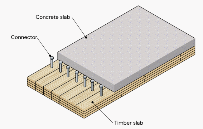
Timber–Concrete Composite (TCC) systems combine timber structural members with a concrete slab connected through mechanical fasteners. The composite interaction between the materials increases stiffness, load capacity, and vibration performance compared to timber-only floor systems.
The SPEC Toolbox Timber–Concrete Composite calculator allows engineers to analyze composite floor systems composed of:
-
CLT timber panels
-
reinforced concrete slab
-
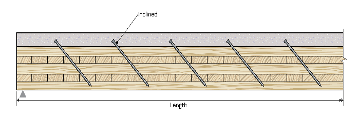
inclined screw connectors
The calculator evaluates:
-
concrete capacity
-
timber capacity
-
connection capacity
-
composite bending behavior
-
deflection performance
-
vibration response
The structural interaction between the timber and concrete layers is modeled using mechanical connectors and composite beam theory, allowing realistic prediction of system behavior.
For the Eurocode region, the calculator uses the following standards:
Design Codes
-
EN 1992-1-1:2004 – Eurocode 2: Design of Concrete Structures
-
EN 1995-1-1:2004 – Eurocode 5: Design of Timber Structures
Loading Code
-
EN 1991:2002 – Eurocode 1: Actions on Structures
These standards define the material models, safety factors, and verification procedures used in the analysis.
Geometry and Components
A timber–concrete composite floor consists of two primary structural components:
-
CLT timber panel
-
concrete slab
The concrete slab resists compressive forces and increases bending stiffness, while the timber panel primarily carries tensile stresses.
The system geometry is defined by:
-
CLT panel layup
-
concrete slab thickness
-
reinforcement parameters
-
connector spacing
-
span length
These parameters determine the composite stiffness and structural performance of the floor system.
The CLT panel is defined using manual layer input, where the user specifies:
-
layer thickness
-
fiber orientation
-
timber grade
-
stacking configuration
This allows modeling of custom CLT configurations.
The concrete layer is defined using:
-
concrete grade
-
concrete thickness
-
cement type
-
relative humidity
These parameters influence the stiffness and long-term behavior of the composite system.
Reinforcement parameters include:
-
reinforcement strength
-
bar diameter
-
reinforcement spacing
These values are used for crack control and reinforcement verification.
Design Methods
Composite behavior between the timber and concrete layers is evaluated using analytical methods that account for connector flexibility.
The calculator supports the following analytical methods:
-
Extended Gamma Method
-
Equivalent Gamma Method
These methods determine the effective bending stiffness of the composite section, considering slip between timber and concrete layers.
Additional design parameters include:
-
composite stiffness factor
-
verification condition (t = 0 and t = ∞)
-
material design factors
These parameters influence the composite structural verification.
Loads
The composite floor is analyzed as a beam system subjected to distributed loads.
Users define:
-
span length
-
support conditions
-
load distribution
The analysis determines:
-
bending stresses
-
shear forces
-
composite section stresses
-
connector shear forces
These values are used for ultimate and serviceability verification.

Vibration Methods
Floor vibration performance is evaluated using available vibration assessment methods.
Available vibration methods:
-
Hamm et al. 2010
-
FPInnovations
-
prEN 1995:2023
Additional vibration parameters include:
-
floor performance level
-
secondary width
-
damping ratio
-
walking frequency
-
floating screed stiffness
-
support condition
These parameters influence the dynamic response of the floor system.

Screw Data
Composite interaction between the timber and concrete layers is achieved using inclined screw connectors.
Users define:
-
fastener type
-
screw orientation (inclined)
-
connector stiffness parameters
Screw properties are defined using manual input, including:
-
screw type
-
tensile strength
-
associated density
-
nominal diameter
-
screw length
-
threaded length
-
inner thread diameter
-
tip length
Connection geometry is defined using:
-
spacing along the beam (a₁)
-
spacing across the beam (a₂)
-
edge distance (a₃)
-
embedment length
-
connector position
These parameters determine the shear transfer capacity between timber and concrete layers.
Design Checks
After the analysis, the calculator provides a complete verification summary.
The following checks are evaluated:
Ultimate Limit State (at t=0 and at t=∞)
-
Concrete capacity
-
Timber capacity
-
Connection design
Serviceability Limit State
-
Deflection
-
Vibration performance
Each verification includes a utilization ratio and pass/fail indicator, allowing engineers to quickly assess the structural performance of the timber–concrete composite system.
Tutorials
CLT Floor-to-Wall Connection Design

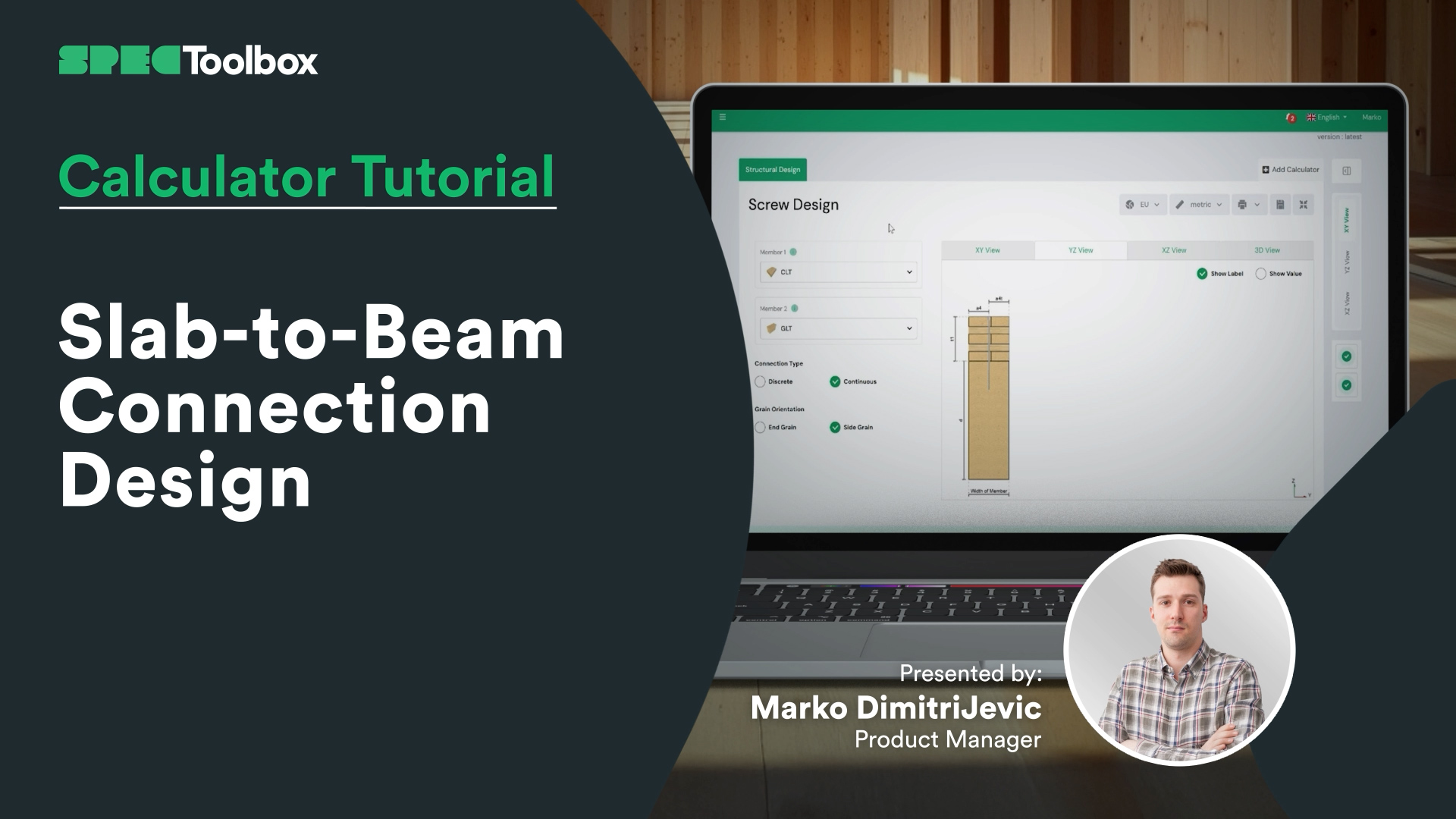
Slab-to-Beam Connection Design
Half-Lap Connection Design
Join us as we break down the Half-Lap joint design, focusing on maintaining structural continuity without external steel plates. Using the Screw Module, we walk through the auto-checking of edge distances and spacing requirements critical for these tight geometric joints.

CLT Wall Calculator
In this video, you’ll learn how to design a typical CLT wall element step by step. We’ll cover selecting a CLT supplier, using the right functionalities, dynamic images, and educational content to determine the optimal panel thickness and design. You’ll also see how to switch between Platform and Balloon framing types, apply different eccentricity methods, and add in-plane and out-of-plane loads -giving you a solid understanding of the basics of CLT wall calculations and design.
Mass timber is shaping the future of sustainable construction. With record-breaking timber buildings emerging worldwide, mastering CLT design is more relevant than ever. Check out our CLT Toolbox app for powerful design tools, automated calculations, and expert insights to help you streamline your CLT projects!

CLT Diaphgram Design Calculator
A complete guide to setting up and analyzing diaphragm behavior in the X-direction using CLT Toolbox. You’ll define screw types for stiffness calculations, set panel geometry, connection types, and panel widths. We cover how to input ULS and SLS forces, and explain required in-plane shear values and lamination data. The video finishes with a breakdown of deflection results, force actions, and strength checks per Eurocode 5.

CLT Floor Fire Design
We’re excited to launch the long-awaited Fire Design module for CLT floors, now available alongside the ambient design calculator on CLT Toolbox.
This tutorial walks through how the new module works, including which standards are supported and how char depth is calculated layer by layer.
Key features include:
- Support for multiple fire models:
– Draft Eurocode 5 (prEN 1995-1-2:2023)
– Austrian National Annex (ÖNORM B EN 1995-1-2:2011)
– Standard Fire Tests (ISO 834 / EN 1363-1) - Flexibility to define protection layers and fire-exposed sides
- Automatic layer-by-layer charring depth calculations over time
- Clear logic for bond-line failure and glue-line degradation
- Full PDF export with all intermediate steps, safety factors and inputs
Built to give engineers transparency, accuracy, and speed for CLT fire design.

CLT Shear Wall Design
Glad to announce that the Second Version Of Our CLT Shear Wall Calculator is now LIVE!
After 12 months of listening to user feedback, we’re excited to release an enhanced and more robust tool for shear wall design.
CLT Shear Walls have excellent in-plane strength and can serve as a reliable lateral load resisting system.
The second version of the calculator includes features such as five cutting-edge load transfer methods—leveraging research from Casagrande, Wallner-Novak, Tomasi, Pei, and Reynolds. We’ve also added lateral deformation checks and panel stiffness calculations following ProHolz 2014 Guide. Finally, we also include the In-plane Design of CLT as according to both Proholz 2014 & FP Innovations 2019.
We’re putting the shear wall calculator on the free version for the month of October. So go to the app to check it out🙂

CLT Floor Design Calculator
Join us as we explore everything from choosing the ideal CLT panel—whether you’re opting for a supplier’s product or manually entering your own data—to selecting the right National Annex, defining loads, and refining the finer details. This video walks you through each stage, including structural analysis, stiffness calculations, and even the integration of edge-glue lamellas into your design.
We’ll also examine how various vibration techniques affect your structure and reveal how you can optimize your design by factoring in the in-plane stiffness of the concrete screed and the influence of flexible support. Plus, you’ll be able to track results and formulas throughout the process, ensuring you’re always in the know.
Let’s get started!

CLT Diaphgram Design Calculator
Get started with a comprehensive approach to diaphragm design by defining forces, material properties, and applying Eurocode 5 parameters. Begin by defining the input forces acting on the diaphragm in the X-direction and selecting screw types for stiffness calculations. Setting the geometry and orientation of the diaphragm in the user inputs, type of panel connections, and panel width with the technical information from CLT suppliers. Input forces for both ULS and SLS, considering force direction. Understand in-plane shear values, required lamination data, and key design parameters for Eurocode 5. Finally, analyze deflection results, the underlying theory, action forces, and strength checks to ensure a precise and efficient design.

Frequently Asked Questions
Why use timber–concrete composite floors?
Timber–concrete composite floors combine the sustainability of timber with the stiffness and mass of concrete. This improves structural stiffness, vibration performance, and load capacity compared to timber-only floors.
Why are mechanical connectors critical in TCC design?
Mechanical connectors control the shear transfer between the concrete slab and the timber member. Their stiffness and spacing determine how effectively the two materials act together as a composite section.

 Dowels
 CLT
CLT Screws
 GLT
GLT Brackets
 Light-frame
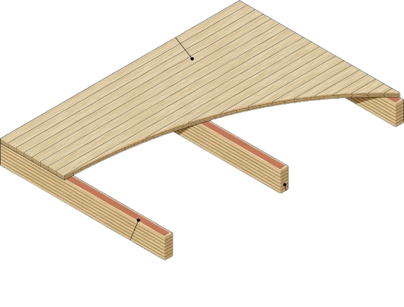 Ribbed Deck
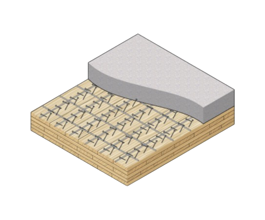 TCC
TCC