
CLT Design Software for AS1720.1 | Engineering Platform
Launch the free CLT Floor Calculator below & verify your design in seconds!
The New Standard for Australian Mass Timber Engineering
CLT Design in Australia is transforming the skyline, yet for many structural engineers, the path to a compliant mass timber design is filled with technical roadblocks. Despite its prevalence, specialized CLT design software for AS1720.1 is rarely taught at the university level, leaving a significant knowledge gap in the local industry.
Designing with the primary Australian timber code, AS1720.1, presents a unique challenge: the standard does not currently contain “Deemed-to-Satisfy” (DtS) provisions for CLT. This forced reliance on a Performance Solution pathway requires engineers to use a verified CLT calculator to manually synthesize first principles with code-specific factors like k1, k4, and k6.
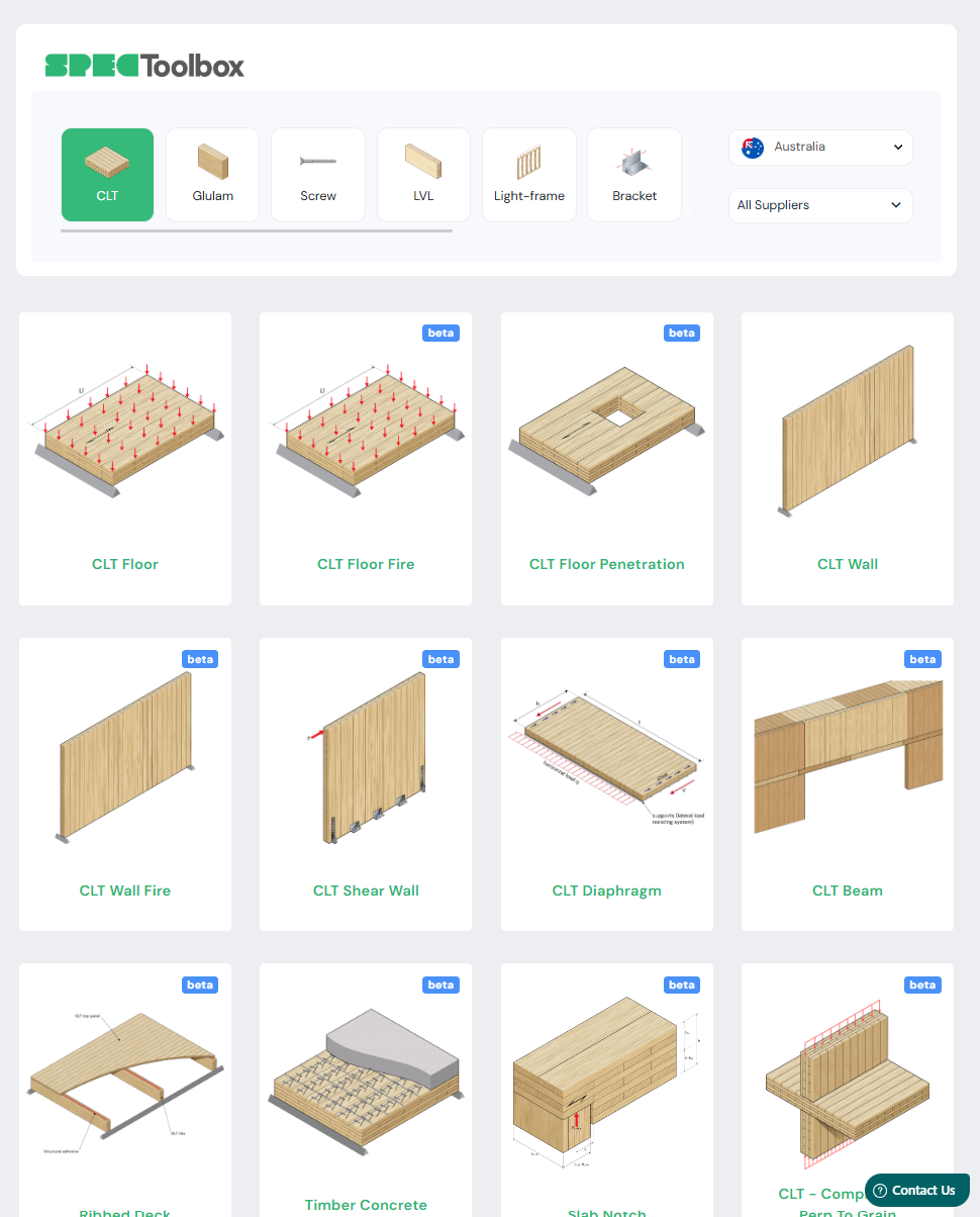
The Australian Engineering Platform for CLT Design
Our platform performs a comprehensive number of checks for CLT design to AS1720. The calculation modules include:

Aggiornamenti dei nostri partner
La piattaforma in più rapida crescita per le specifiche del legname
Key CLT Design Capabilities
Design of CLT Floors
Universal Supplier & Code Integration
Effective floor design begins with the CLT supplier. Our platform allows you to toggle seamlessly between local and international data:
-
Australian Standards: Automatically apply AS1720.1 modification factors such as k1, k4, and k6 for local products like XLam and NeXTimber.
-
Eurocode Compliance: For European suppliers like KLH or Binderholz, the platform applies Eurocode 5 factors including kmod and γm, ensuring the right approach for imported CLT.
Analytical Methods for CLT Stiffness
-
The Gamma Method: Best for standard, uniform CLT panels with 3, 5, or 7 layers. It accounts for the rolling shear deformation in the cross-layers by using a simplified efficiency factor.
-
The Extended Gamma Method: Our recommended method for thick panels (7-ply and above) or non-uniform layups. It provides a more refined calculation of effective stiffness by accounting for the rolling shear stiffness of every individual cross-layer, preventing overly conservative designs.
-
The Shear Analogy Method: The most rigorous analytical approach, suitable for highly complex or asymmetric layups. It treats the panel as a composite beam with distinct bending and shear stiffness components, providing the highest level of accuracy for all layup configurations.
High-Performance Vibration Design
Vibration is often the governing serviceability limit state for CLT floors. We have included the latest Eurocode drafts to provide a superior design outcome:
-
Support Conditions: Model realistic scenarios including stiff or flexible supports to accurately predict floor behavior.
-
Performance Levels: Specify target performance levels to meet specific building requirements, moving beyond simple frequency checks to holistic occupant comfort.
This calculator goes beyond simple static deflection. The tool analyzes the Fundamental Frequency (f1) and Impulsive Velocity Response, allowing you to tune the floor mass and stiffness to meet strict vibration criteria (e.g., 8Hz for offices), ensuring the “feel” of the floor matches the quality of the building.

Design of CLT Fire
Advanced CLT Fire Engineering
Structural fire design for mass timber is a critical component of any NCC 2025 Performance Solution.
SPEC Toolbox simplifies this complexity by offering multiple verification pathways aiding engineering judgement, ranging from the widely adopted ÖNORM B EN 1995-1-2:2011 (Austrian National Annex) to the cutting-edge prEN1995-1-2:2023 (2nd Generation Eurocode). Whether you are utilizing a standard fire curve or a physically based fire model, the platform calculates precise charring depths and residual load-bearing capacities, helping your CLT panels meet stringent safety and integrity requirements.
Precision Charring & Bond-Line Integrity
Our engine accounts for the sophisticated physics of timber charring, moving beyond simple uniform rates. You can define the basic charring rate based on timber density and moisture content, and the platform automatically applies relevant ki factors to determine notional rates. Crucially, our 2nd Generation Eurocode module explicitly models bond-line integrity and gap effects, preventing the catastrophic loss of protection often ignored in simplified calculations.
Automated Factor Analysis for Performance Solutions
To provide total engineering transparency, SPEC Toolbox enables granular control over charring variables. The platform automates the calculation of Char Factors, including the GAP coefficient and specific k2, k3, and kg values required for layered protection systems. This “No Black Box” approach allows engineers to either use code-specific defaults or bypass them with manual inputs from manufacturer fire tests, creating a verified path from first principles to project certification.

Design of CLT Connections
1. Moving Beyond AS1720.1 Limitations
While AS1720.1 is the current Australian standard, it is widely recognized as having limitations regarding modern mass timber connections.
-
Advanced Yield Modeling: SPEC Toolbox utilizes the latest Eurocode methodologies, including the Johansen Yield Models, to provide more accurate and appropriate design outcomes than simplified local methods.
-
ETA Integration: We integrate supplier-specific European Technical Assessments (ETAs), ensuring your designs utilize ultimate performance data unique to specific product families.
2. Simplified Screw & Joint Design
Our platform transforms complex connection math into a streamlined, high-speed workflow:
-
Preconfigured Joint Types: Rapidly design and verify Half Laps, Splines, and Butt Joints with automated geometry checks.
-
Steel-to-CLT: Specialized modules for timber-to-steel connections, handling the complex stress distributions at the interface.
3. The “Global-Local” Connection Library
SPEC Toolbox is the only platform that allows you to pair your choice of CLT Supplier with the world’s leading Connection Manufacturers:
-
Universal Fastener Selection: Choose from top-tier brands including Rothoblaas, Spax, Eurotec, Sihga, Klimas, Simpson Strong-Tie, or Anzor.
-
Verified Compatibility: Seamlessly verify these fasteners against local and European panels like XLam, NeXTimber, or Red Stag.

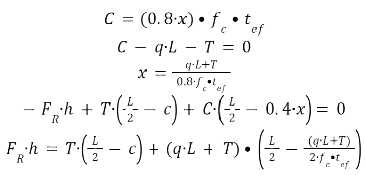
Design of CLT Shear Walls
In-plane CLT Design
ProHolz vol 1 Clause 5.8
ProHolz identifies three failure mechanisms for CLT shear walls:
- Mechanism 1: Shearing of failure of the boards along a joint
- Mechanism 2: Shearing failure of the glued surface at the intersection of joints.
- Mechanism 3: Shearing failure of the entire plate.
FP innovation Clause 3.8
By considering the shear stresses in the lamellas and the crossing areas, three different failure modes exist in CLT beams subjected to shear stresses such as
- Failure Mode I: Shear failure parallel to the grain in the gross cross-section
- Failure Mode II: Shear failure perpendicular to the grain in the net cross-section
- Failure Mode III: Shear failure in crossing area of orthogonal lamination
Wall Connection Models
In summary of the methods that are used to determine the capacity of the CLT shear wall at the connection points include:
| Metodi | Sommario | |
| Method I, Casagrande et al. 2016 | Analizza le pareti di taglio utilizzando la rotazione dei corpi rigidi e l'equilibrio statico, con il punto di rotazione sul bordo del pannello, concentrandosi sul bilanciamento delle forze interne. |
|
| Method II, Wallner-Novak et al. 2014 |
Utilizza un blocco di sollecitazione rettangolare semplificato e tiene conto della resistenza di attrito, fornendo un approccio più dettagliato alla resistenza allo scorrimento.
|
|
| Method III, Tomasi, 2014 |
Simile al metodo Wallner-Novak, ma con una lunghezza della zona di compressione diversa e presuppone una fondazione estremamente rigida con un calcolo raffinato dell'asse neutro.
|
|
| Method IV, Pei et al. 2012 |
Tratta il pannello CLT come un corpo rigido che ruota attorno a un angolo con connettori modellati come molle elastiche, basandosi sulla resistenza di connessione calibrata a posteriori ed escludendo dalla analisi la resistenza allo scorrimento.
|
|
| Method V, Reynolds et al. 2017 |
Migliora il metodo di distribuzione triangolare della tensione includendo una zona di compressione e tenendo conto dell'attrito per migliorare la valutazione della resistenza allo scorrimento.
|


The Ultimate CLT Desing Platform for Australian Structural Engineers
If you’re looking to design CLT on your next project, then SPEC Toolbox has you covered!
Tutorials
CLT Floor-to-Wall Connection Design

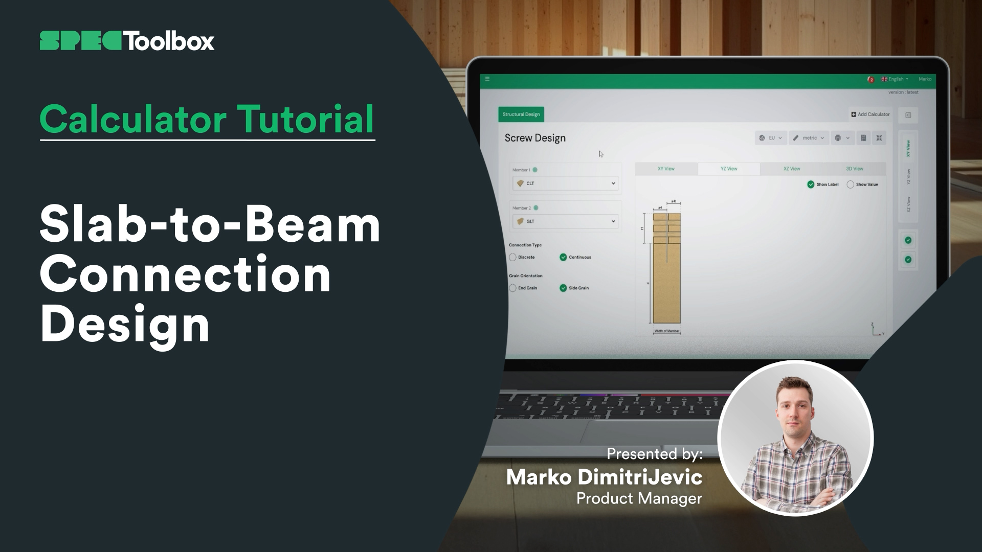
Slab-to-Beam Connection Design
Half-Lap Connection Design
Join us as we break down the Half-Lap joint design, focusing on maintaining structural continuity without external steel plates. Using the Screw Module, we walk through the auto-checking of edge distances and spacing requirements critical for these tight geometric joints.

Calcolatore per pareti CLT
In questo video imparerai come progettare passo dopo passo un tipico elemento murario in CLT. Tratteremo la selezione di un fornitore di CLT, l'utilizzo delle giuste funzionalità, immagini dinamiche e contenuti didattici per determinare lo spessore e il design ottimali del pannello. Vedrai anche come passare dai tipi di intelaiatura Platform a Balloon, applicare diversi metodi di eccentricità e aggiungere carichi in piano e fuori piano, acquisendo una solida comprensione delle basi del calcolo e della progettazione delle pareti in CLT.
Il legno massiccio sta plasmando il futuro dell'edilizia sostenibile. Con la diffusione di edifici in legno da record in tutto il mondo, padroneggiare la progettazione CLT è più importante che mai. Scopri la nostra app CLT Toolbox per potenti strumenti di progettazione, calcoli automatizzati e approfondimenti di esperti che ti aiuteranno a semplificare i tuoi progetti CLT!

Calcolatore per la progettazione di diaframmi CLT
Una guida completa alla configurazione e all'analisi del comportamento del diaframma nella direzione X utilizzando CLT Toolbox. Definirete i tipi di viti per i calcoli di rigidità, imposterete la geometria dei pannelli, i tipi di connessione e le larghezze dei pannelli. Tratteremo come inserire le forze ULS e SLS e spiegheremo i valori di taglio nel piano e i dati di laminazione richiesti. Il video si conclude con un'analisi dei risultati di deflessione, delle azioni delle forze e dei controlli di resistenza secondo l'Eurocodice 5.

Progettazione antincendio per pavimenti in CLT
Siamo lieti di lanciare il tanto atteso modulo Fire Design per pavimenti in CLT, ora disponibile insieme al calcolatore di progettazione ambientale su CLT Toolbox.
Questo tutorial illustra il funzionamento del nuovo modulo, compresi gli standard supportati e il calcolo della profondità dei caratteri strato per strato.
Key features include:
- Support for multiple fire models:
– Draft Eurocode 5 (prEN 1995-1-2:2023)
– Austrian National Annex (ÖNORM B EN 1995-1-2:2011)
– Standard Fire Tests (ISO 834 / EN 1363-1) - Flexibility to define protection layers and fire-exposed sides
- Automatic layer-by-layer charring depth calculations over time
- Clear logic for bond-line failure and glue-line degradation
- Full PDF export with all intermediate steps, safety factors and inputs
Realizzato per garantire agli ingegneri trasparenza, precisione e rapidità nella progettazione antincendio dei CLT.

Progettazione di pareti di taglio in CLT
Siamo lieti di annunciare che la seconda versione del nostro calcolatore per pareti di taglio CLT è ora DISPONIBILE!
Dopo 12 mesi passati ad ascoltare i feedback degli utenti, siamo lieti di presentare uno strumento migliorato e più robusto per la progettazione di pareti di taglio.
Le pareti di taglio CLT hanno un'eccellente resistenza nel piano e possono fungere da affidabile sistema di resistenza ai carichi laterali.
La seconda versione del calcolatore include funzionalità quali cinque metodi all'avanguardia per il trasferimento dei carichi, basati sulle ricerche di Casagrande, Wallner-Novak, Tomasi, Pei e Reynolds. Abbiamo anche aggiunto controlli di deformazione laterale e calcoli di rigidità dei pannelli secondo la guida ProHolz 2014. Infine, abbiamo incluso anche la progettazione in piano del CLT secondo Proholz 2014 e FP Innovations 2019.
Per tutto il mese di ottobre, il calcolatore per pareti di taglio sarà disponibile nella versione gratuita. Vai sull'app per provarlo🙂

Calcolatore per la progettazione di pavimenti in CLT
Unitevi a noi mentre esploriamo tutto, dalla scelta del pannello CLT ideale, sia che optiate per il prodotto di un fornitore o che inseriate manualmente i vostri dati, alla selezione dell'allegato nazionale corretto, alla definizione dei carichi e alla messa a punto dei dettagli più precisi. Questo video vi guida attraverso ogni fase, compresa l'analisi strutturale, i calcoli di rigidità e persino l'integrazione delle lamelle incollate ai bordi nel vostro progetto.
Esamineremo anche come le varie tecniche di vibrazione influiscono sulla struttura e riveleremo come è possibile ottimizzare il progetto tenendo conto della rigidità nel piano del massetto in calcestruzzo e dell'influenza del supporto flessibile. Inoltre, sarà possibile monitorare i risultati e le formule durante tutto il processo, assicurandosi di essere sempre informati.
Cominciamo!

Calcolatore per la progettazione di diaframmi CLT
Inizia con un approccio completo alla progettazione del diaframma definendo le forze, le proprietà dei materiali e applicando i parametri dell'Eurocodice 5. Inizia definendo le forze di input che agiscono sul diaframma nella direzione X e selezionando i tipi di viti per i calcoli di rigidità. Imposta la geometria e l'orientamento del diaframma negli input dell'utente, il tipo di connessioni dei pannelli e la larghezza dei pannelli con le informazioni tecniche fornite dai fornitori di CLT. Forze di input sia per ULS che per SLS, tenendo conto della direzione della forza. Comprendere i valori di taglio nel piano, i dati di laminazione richiesti e i parametri di progettazione chiave per l'Eurocodice 5. Infine, analizzare i risultati della deflessione, la teoria sottostante, le forze di azione e i controlli di resistenza per garantire una progettazione precisa ed efficiente.

Frequently Asked Questions
What is the best method to calculate the stiffness for CLT?
The Standard Gamma method assumes a regular distribution of stiffness. The Extended Gamma Method is required for accurate results when using layups with varying layer thickness or modulus of elasticity (MOE), ensuring you don’t overestimate the floor’s stiffness.
The Shear Analogy method from North America uses a fundamentally different analogy, incorporating shear deformation into the equation. If unsure, we recommend going with the Extended Gamma Method.
Does this platform enable "Deemed-to-Satisfy" (DtS) engineering?
Not strictly. Since CLT is not fully prescriptive in AS 1720.1 yet, our tools are designed to support a Performance Solution. It generates the engineering data required to prove compliance with the NCC’s Performance Requirements.

 CLT
CLT Dowels
 GLT
GLT Viti
Viti Staffe
 Light-frame