
Timber Concrete Composite (TCC) Design Software for AS1720.1 | Engineering Platform
Launch the free Timber Concrete Composite (TCC) Calculator below & verify your design in seconds!
The New Standard for Australian Mass Timber Engineering
Timber–Concrete Composite (TCC) floor systems are gaining increasing attention as engineers seek solutions that combine the sustainability of timber with the stiffness and mass of concrete. By integrating a concrete slab with timber panels through mechanical connectors, TCC systems can significantly improve structural stiffness, vibration performance, and load-carrying capacity compared to timber-only floors.
Despite these advantages, designing timber–concrete composite floors remains complex. The structural behaviour depends on the interaction between timber, concrete, and the shear connectors that transfer forces between the two materials. This composite interaction must be carefully evaluated to accurately predict bending stiffness, internal force distribution, and long-term performance.
Under the Eurocode framework, TCC systems are typically designed using EN 1992-1-1 – Eurocode 2 (Concrete Structures) together with EN 1995-1-1 – Eurocode 5 (Timber Structures). Because composite timber–concrete floors are not covered by simplified “Deemed-to-Satisfy” provisions, engineers often rely on analytical approaches such as the Gamma Method or Extended Gamma Method to model partial composite action and verify structural capacity, serviceability, and connection performance.
The Australian Engineering Platform for Timber Concrete Composite (TCC) Design
Our platform performs a check for Timber–Concrete Composite (TCC) Design to AS1720. The calculation module include:

Unsere Partner-Updates
Die am schnellsten wachsende Plattform für Holzspezifikationen
Key Timber–Concrete Composite Design (TCC) Design Capabilities
Overview of Timber–Concrete Composite Systems
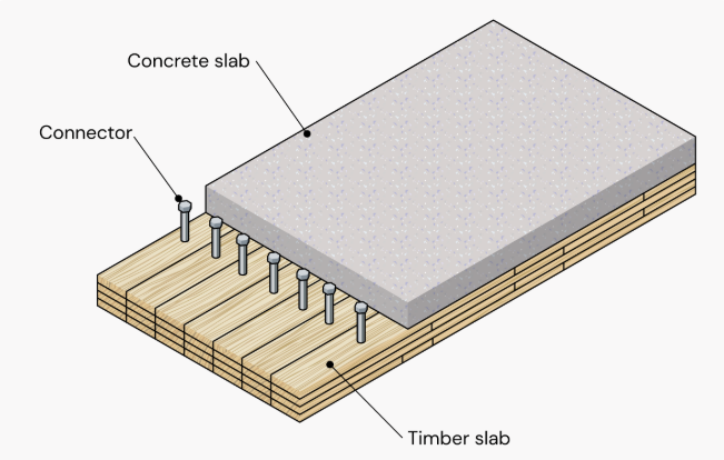
Timber–Concrete Composite (TCC) systems combine timber structural members with a concrete slab connected through mechanical fasteners. The composite interaction between the materials increases stiffness, load capacity, and vibration performance compared to timber-only floor systems.
The SPEC Toolbox Timber–Concrete Composite calculator allows engineers to analyze composite floor systems composed of:
-
CLT timber panels
-
reinforced concrete slab
-
inclined screw connectors
The calculator evaluates:
-
concrete capacity
-
timber capacity
-
connection capacity
-
composite bending behavior
-
deflection performance
-
vibration response
The structural interaction between the timber and concrete layers is modeled using mechanical connectors and composite beam theory, allowing realistic prediction of system behavior.
For the Eurocode region, the calculator uses the following standards:
Design Codes
-
EN 1992-1-1:2004 – Eurocode 2: Design of Concrete Structures
-
EN 1995-1-1:2004 – Eurocode 5: Design of Timber Structures
Loading Code
-
EN 1991:2002 – Eurocode 1: Actions on Structures
These standards define the material models, safety factors, and verification procedures used in the analysis.
Geometry and Components
A timber–concrete composite floor consists of two primary structural components:
-
CLT timber panel
-
concrete slab
The concrete slab resists compressive forces and increases bending stiffness, while the timber panel primarily carries tensile stresses.
The system geometry is defined by:
-
CLT panel layup
-
concrete slab thickness
-
reinforcement parameters
-
connector spacing
-
span length
These parameters determine the composite stiffness and structural performance of the floor system.
The CLT panel is defined using manual layer input, where the user specifies:
-
layer thickness
-
fiber orientation
-
timber grade
-
stacking configuration
This allows modeling of custom CLT configurations.
The concrete layer is defined using:
-
concrete grade
-
concrete thickness
-
cement type
-
relative humidity
These parameters influence the stiffness and long-term behavior of the composite system.
Reinforcement parameters include:
-
reinforcement strength
-
bar diameter
-
reinforcement spacing
These values are used for crack control and reinforcement verification.
Design Methods
Composite behavior between the timber and concrete layers is evaluated using analytical methods that account for connector flexibility.
The calculator supports the following analytical methods:
-
Extended Gamma Method
-
Equivalent Gamma Method
These methods determine the effective bending stiffness of the composite section, considering slip between timber and concrete layers.
Additional design parameters include:
-
composite stiffness factor
-
verification condition (t = 0 and t = ∞)
-
material design factors
These parameters influence the composite structural verification.
Loads
The composite floor is analyzed as a beam system subjected to distributed loads.
Users define:
-
span length
-
support conditions
-
load distribution
The analysis determines:
-
bending stresses
-
shear forces
-
composite section stresses
-
connector shear forces
These values are used for ultimate and serviceability verification.

Vibration Methods
Floor vibration performance is evaluated using available vibration assessment methods.
Available vibration methods:
-
Hamm et al. 2010
-
FPInnovations
-
prEN 1995:2023
Additional vibration parameters include:
-
floor performance level
-
secondary width
-
damping ratio
-
walking frequency
-
floating screed stiffness
-
support condition
These parameters influence the dynamic response of the floor system.

Screw Data
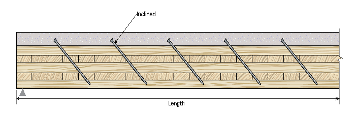
Composite interaction between the timber and concrete layers is achieved using inclined screw connectors.
Users define:
-
fastener type
-
screw orientation (inclined)
-
connector stiffness parameters
Screw properties are defined using manual input, including:
-
screw type
-
tensile strength
-
associated density
-
nominal diameter
-
screw length
-
threaded length
-
inner thread diameter
-
tip length
Connection geometry is defined using:
-
spacing along the beam (a₁)
-
spacing across the beam (a₂)
-
edge distance (a₃)
-
embedment length
-
connector position
These parameters determine the shear transfer capacity between timber and concrete layers.
Design Checks
After the analysis, the calculator provides a complete verification summary.
The following checks are evaluated:
Ultimate Limit State (at t=0 and at t=∞)
-
Concrete capacity
-
Timber capacity
-
Connection design
Serviceability Limit State
-
Durchbiegung
-
Vibration performance
Each verification includes a utilization ratio and pass/fail indicator, allowing engineers to quickly assess the structural performance of the timber–concrete composite system.
Tutorials
CLT Floor-to-Wall Connection Design

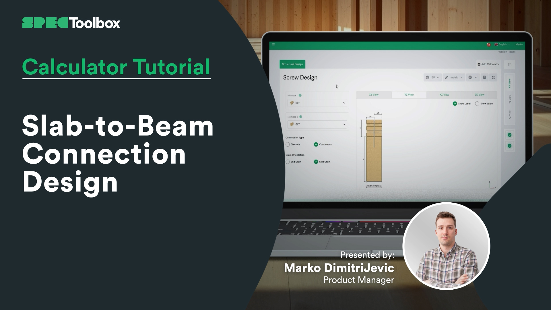
Slab-to-Beam Connection Design
Half-Lap Connection Design
Join us as we break down the Half-Lap joint design, focusing on maintaining structural continuity without external steel plates. Using the Screw Module, we walk through the auto-checking of edge distances and spacing requirements critical for these tight geometric joints.

CLT-Wandrechner
In diesem Video lernen Sie Schritt für Schritt, wie Sie ein typisches CLT-Wandelement entwerfen. Wir behandeln die Auswahl eines CLT-Lieferanten, die Verwendung der richtigen Funktionen, dynamische Bilder und Lehrinhalte, um die optimale Plattendicke und das optimale Design zu bestimmen. Außerdem erfahren Sie, wie Sie zwischen den Rahmenkonstruktionstypen „Platform“ und „Balloon“ wechseln, verschiedene Exzentrizitätsmethoden anwenden und Lasten innerhalb und außerhalb der Ebene hinzufügen können. So erhalten Sie ein solides Verständnis der Grundlagen der Berechnung und Konstruktion von CLT-Wänden.
Massivholz prägt die Zukunft des nachhaltigen Bauens. Angesichts der weltweit immer zahlreicher werdenden Rekord-Holzgebäude ist die Beherrschung der CLT-Konstruktion wichtiger denn je. Entdecken Sie unsere CLT Toolbox App mit leistungsstarken Konstruktionswerkzeugen, automatisierten Berechnungen und Expertenwissen, die Ihnen helfen, Ihre CLT-Projekte zu optimieren!

CLT-Membran-Konstruktionsrechner
Eine vollständige Anleitung zum Einrichten und Analysieren des Verhaltens von Membranen in X-Richtung mit der CLT Toolbox. Sie definieren Schraubentypen für Steifigkeitsberechnungen, legen die Plattengeometrie, Verbindungstypen und Plattenbreiten fest. Wir behandeln die Eingabe von ULS- und SLS-Kräften und erläutern die erforderlichen Werte für die Scherkräfte in der Ebene sowie die Laminierungsdaten. Das Video endet mit einer Aufschlüsselung der Durchbiegungsergebnisse, Kraftwirkungen und Festigkeitsprüfungen gemäß Eurocode 5.

CLT-Boden Brandschutzkonzept
Wir freuen uns, das lang erwartete Brandschutzmodul für CLT-Böden vorstellen zu können, das nun neben dem Raumklima-Rechner in der CLT Toolbox verfügbar ist.
Dieses Tutorial erklärt, wie das neue Modul funktioniert, welche Standards unterstützt werden und wie die Zeichentiefe Schicht für Schicht berechnet wird.
Key features include:
- Support for multiple fire models:
– Draft Eurocode 5 (prEN 1995-1-2:2023)
– Austrian National Annex (ÖNORM B EN 1995-1-2:2011)
– Standard Fire Tests (ISO 834 / EN 1363-1) - Flexibility to define protection layers and fire-exposed sides
- Automatic layer-by-layer charring depth calculations over time
- Clear logic for bond-line failure and glue-line degradation
- Full PDF export with all intermediate steps, safety factors and inputs
Entwickelt, um Ingenieuren Transparenz, Genauigkeit und Schnelligkeit bei der Brandschutzplanung für CLT zu bieten.

CLT-Scherwandkonstruktion
Wir freuen uns, Ihnen mitteilen zu können, dass die zweite Version unseres CLT-Scherwandrechners jetzt LIVE ist!
Nach 12 Monaten, in denen wir uns das Feedback der Nutzer angehört haben, freuen wir uns, ein verbessertes und robusteres Tool für die Bemessung von Schubwänden vorstellen zu können.
CLT-Scherwände verfügen über eine ausgezeichnete Festigkeit in der Ebene und können als zuverlässiges System zur Aufnahme von seitlichen Lasten dienen.
Die zweite Version des Rechners umfasst Funktionen wie fünf hochmoderne Lastübertragungsmethoden, die auf den Forschungsergebnissen von Casagrande, Wallner-Novak, Tomasi, Pei und Reynolds basieren. Außerdem haben wir seitliche Verformungsprüfungen und Berechnungen der Plattensteifigkeit gemäß dem ProHolz-Leitfaden 2014 hinzugefügt. Schließlich haben wir auch die In-Plane-Auslegung von CLT gemäß Proholz 2014 und FP Innovations 2019 integriert.
Wir bieten den Schubwandrechner im Oktober in der kostenlosen Version an. Schauen Sie sich die App doch einmal an 🙂

CLT-Bodenkonstruktionsrechner
Begleiten Sie uns auf unserer Entdeckungsreise, die von der Auswahl der idealen CLT-Platte – egal, ob Sie sich für das Produkt eines Lieferanten entscheiden oder Ihre eigenen Daten manuell eingeben – über die Auswahl des richtigen National Annex bis hin zur Definition der Lasten und der Feinabstimmung der Details reicht. Dieses Video führt Sie durch alle Phasen, einschließlich der Strukturanalyse, der Steifigkeitsberechnungen und sogar der Integration von Kantenleimlamellen in Ihr Design.
Wir untersuchen auch, wie sich verschiedene Rütteltechniken auf Ihre Konstruktion auswirken, und zeigen Ihnen, wie Sie Ihr Design optimieren können, indem Sie die Ebenesteifigkeit des Betonestrichs und den Einfluss flexibler Stützen berücksichtigen. Außerdem können Sie die Ergebnisse und Formeln während des gesamten Prozesses verfolgen, sodass Sie immer auf dem Laufenden sind.
Fangen wir an!

CLT-Membran-Konstruktionsrechner
Beginnen Sie mit einem umfassenden Ansatz für die Membrankonstruktion, indem Sie Kräfte und Materialeigenschaften definieren und die Parameter des Eurocode 5 anwenden. Beginnen Sie mit der Definition der auf die Membran in X-Richtung einwirkenden Eingangskräfte und der Auswahl der Schraubentypen für die Steifigkeitsberechnungen. Legen Sie die Geometrie und Ausrichtung der Membran in den Benutzereingaben, die Art der Plattenverbindungen und die Plattenbreite anhand der technischen Informationen der CLT-Lieferanten fest. Geben Sie Kräfte für ULS und SLS unter Berücksichtigung der Kraftrichtung ein. Machen Sie sich mit den Scherkräften in der Ebene, den erforderlichen Laminierungsdaten und den wichtigsten Entwurfsparametern für Eurocode 5 vertraut. Analysieren Sie abschließend die Durchbiegungsergebnisse, die zugrunde liegende Theorie, die Wirkungskräfte und die Festigkeitsprüfungen, um einen präzisen und effizienten Entwurf sicherzustellen.

Frequently Asked Questions
Why use timber–concrete composite floors?
Timber–concrete composite floors combine the sustainability of timber with the stiffness and mass of concrete. This improves structural stiffness, vibration performance, and load capacity compared to timber-only floors.
Why are mechanical connectors critical in TCC design?
Mechanical connectors control the shear transfer between the concrete slab and the timber member. Their stiffness and spacing determine how effectively the two materials act together as a composite section.

 Dowels
 CLT
CLT Schrauben
 GLT
GLT Klammern
 Light-frame
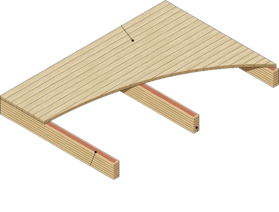 Geriffeltes Deck
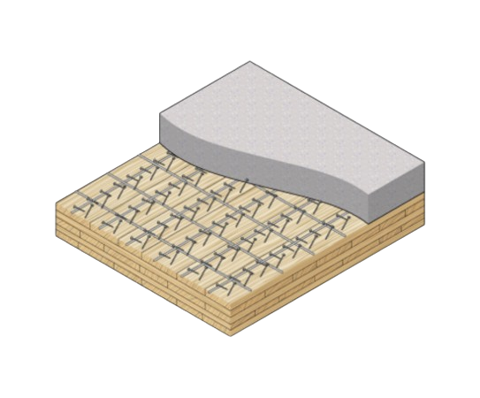 TCC
TCC