
Wood Screw Design Software to Eurocode 5
Use our free web calculator & learn everything you need to know about screw design to Eurocode 5! Second Generation Eurocodes included.
A Timber Engineering Platform Automating Your Screw Design
The Eurocode 5 Screw Calculator is the only engineering tool built for the transition to the Second Generation Eurocode. It calculates the Design Load-Carrying Capacity (Fv,Rd) and Axial Withdrawal Capacity (Fax,Rd) of fasteners while integrating the expanded scope of prEN 1995-1-1 regarding Cross-Laminated Timber (CLT) and brittle failure modes.
Viktiga funktioner:

Våra partneruppdateringar
Den snabbast växande plattformen för trävaruspecifikationer
Key Screw Design Module Capabilities
Overview of Structural Screw Connections
Self-tapping screws are widely used in modern timber engineering for transferring axial and shear forces between structural elements. These fasteners provide high load-bearing capacity, simple installation, and versatile connection configurations for timber-to-timber and timber-to-steel joints.
The SPEC Toolbox Screw Design module allows engineers to evaluate screw connections in a wide range of timber structures using manufacturer-specific fastener data. The calculator integrates real screw geometries and product libraries from leading suppliers, enabling accurate modelling of screw behaviour and load transfer.
The tool supports different timber materials and connection types commonly used in timber construction.
Supported member materials include:
-
Softwood
-
Hardwood
-
Glulam (GLT)
-
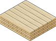
Cross-Laminated Timber (CLT)
-
Laminated Veneer Lumber (LVL)
-
Plywood
-
Steel plates for timber-to-steel connections
This flexibility allows engineers to evaluate connections in both traditional timber structures and modern engineered timber systems.
Interactive Connection Model
To assist with connection configuration, the calculator provides an interactive 3D visualization of the screw arrangement and connected members.
The model shows:
-
screw orientation
-
load directions
-
member geometry
-
fastener placement
Users can rotate and inspect the connection to clearly understand the load transfer mechanism and screw positioning.
This visual feedback helps engineers verify the geometry of the connection before performing structural verification.
Primary and Secondary Member Definition
The calculator allows engineers to define the structural members involved in the connection.
Two members can be configured:
-
Member 1 – primary structural element
-
Member 2 – secondary element or connected member
For each member, the following properties can be defined:
-
member material type
-
member dimensions
-
characteristic timber density (ρk)
-
mean density (ρmean)
The density values are used to calculate the embedment strength of the timber and therefore influence the resistance of the screw connection.
Additionally, the grain orientation relative to the screw can be defined to correctly represent load transfer behaviour in the timber.
Applied Forces
The screw connection may be subjected to axial and shear forces acting in multiple directions.
The calculator allows engineers to define the applied loads acting on the connection, including:
-
Fx – shear force in the x-direction
-
Fy – shear force in the y-direction
-
Fz – axial force acting along the screw axis
These load components represent the design actions acting on the connection according to the selected design standard.
The combined shear force is automatically calculated and used for connection verification.
The applied loads are visualized in the connection model to clearly illustrate their direction and point of application.
Supplier and Product Library
The calculator integrates screw data from recognized manufacturers, allowing engineers to select fasteners directly from supplier product libraries.
Users can define:
-
screw supplier
-
screw family
-
specific screw type
Each screw type includes predefined mechanical properties such as:
-
diameter
-
thread configuration
-
strength properties
-
withdrawal resistance parameters
This integration ensures that the design calculations are based on realistic fastener properties and certified manufacturer data.
Screw Type and Thread Configuration
Different screw configurations can be selected depending on the connection requirements.
Available options include:
-
Partially threaded screws
-
Fully threaded screws
Thread configuration affects the load transfer mechanism and determines whether the screw primarily resists shear forces, axial forces, or combined loading.
The calculator also supports smart screw length selection, helping engineers choose appropriate fastener lengths based on the connection geometry.
Supported Design Methods
Screw connections are evaluated according to Eurocode 5 design provisions for timber connections.
The calculator currently supports three design methodologies:
-
EN 1995-1-1:2004 (Eurocode 5)
Standard design approach for timber connections using dowel-type fasteners. -
prEN 1995:2023
The upcoming revision of Eurocode 5, introducing updated design provisions and calculation models. -
EN 1995-1-1:2004 (Supplier ETA)
Design approach based on manufacturer-specific European Technical Assessment (ETA) values for proprietary fasteners.
These design methods allow engineers to evaluate screw performance according to either general Eurocode rules or manufacturer-certified design data.
Screw Arrangement and Spacing
The geometric arrangement of screws strongly influences the resistance and failure modes of timber connections.
The calculator allows engineers to configure screw placement using two approaches:
Manual Arrangement
Engineers can manually define the screw layout, including:
-
screw spacing
-
edge distances
-
number of screws along different directions
Minimum Distance and Spacing Rules
Alternatively, the calculator can automatically apply Eurocode minimum spacing requirements, ensuring that screw placement satisfies geometric design rules.
Parameters considered include:
-
spacing parallel to grain
-
spacing perpendicular to grain
-
edge distances
-
end distances
-
fastener positioning relative to member geometry
These geometric checks ensure that brittle timber failure modes such as splitting are avoided.
Connection Capacity Checks
After defining the screw configuration, timber properties, and applied loads, the calculator performs structural verification of the connection.
The output summary includes the following checks:
Geometry Check
This verification ensures that screw spacing and edge distances satisfy Eurocode geometric requirements for timber connections.
Shear Capacity
The shear resistance of the screw connection is evaluated according to Eurocode dowel-type fastener models.
Axial Capacity
The axial resistance of the screw is evaluated based on withdrawal resistance and fastener properties.
Combined Actions
When axial and shear forces act simultaneously, the calculator verifies the combined loading condition to ensure the connection capacity is not exceeded.
Slip Modulus
The module also provides the slip modulus of the screw connection, representing the stiffness of the fastener under load. This parameter is important for structural modelling and deformation analysis.
Tutorials
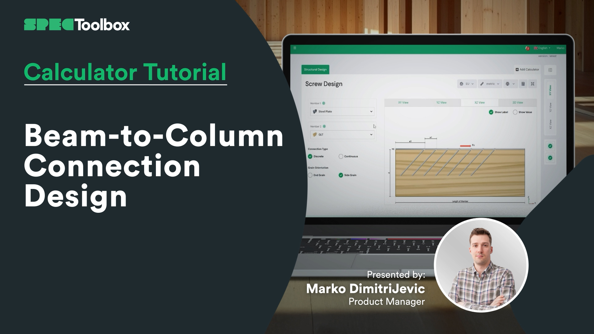
Beam-to-Column Connection Design
Beam-to-Column Connection Tackle the complexity of Beam-to-Column joints in this focused tutorial. We demonstrate how to replace complex bespoke steelwork with smart screw arrangements. Using the Screw Module, we verify the capacity of inclined screw groups to handle significant shear loads directly at the support interface.
Key Screw Benefits:
Crossed-Screw Configurations: Shows how arranging screws in crossed pairs (X-formation) significantly boosts stiffness.
Ductility & Safety: detailed look at how modern structural screws provide necessary ductility for safe, predictable failure modes.
CLT Floor-to-Wall Connection Design

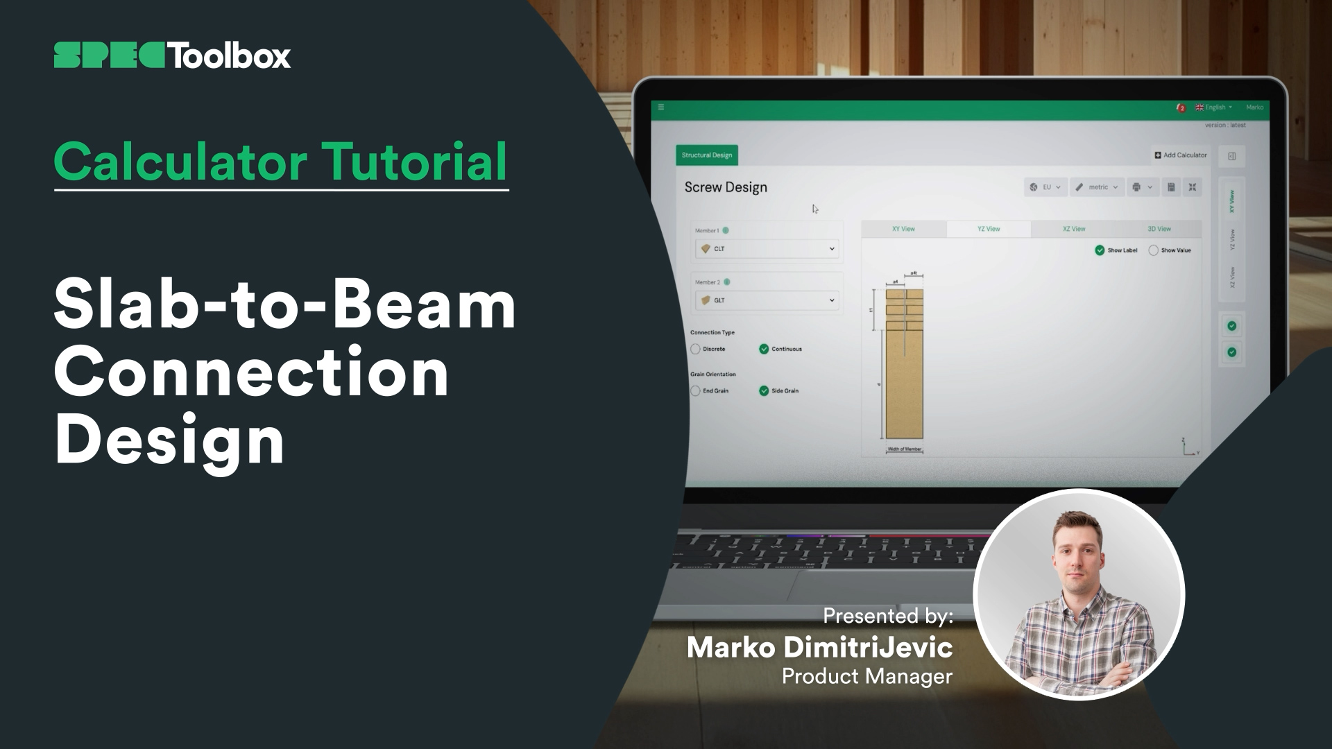
Slab-to-Beam Connection Design
Half-Lap Connection Design
Join us as we break down the Half-Lap joint design, focusing on maintaining structural continuity without external steel plates. Using the Screw Module, we walk through the auto-checking of edge distances and spacing requirements critical for these tight geometric joints.

Skruvar: Sidobelastat trä mot träändträ
Vi är glada över att kunna lansera modulen Laterally Loaded Timber-to-Timber End Grain, ett kraftfullt verktyg för ingenjörer som konstruerar skruvförband som utsätts för sidokrafter. Denna specialiserade kalkylator garanterar noggrannhet och flexibilitet vid konstruktion av träförband.
Viktiga funktioner:
• Konstruktionsnormer: Stöder tre konstruktionsnormer för skruvar med sidobelastning: EN 1995:2004, AS 1720:2010 och prEN 1995:2023.
• Leverantörsinmatning: Mata in skruvar från ledande leverantörer som Rothoblass, Eurotec, Sihga, Spax och Simpson’s Strong Tie.
• Manuell inmatning: Möjliggör manuell inmatning av skruvparametrar, inklusive dimensioner och materialegenskaper.
• Flexibla beräkningar: Utför beräkningar baserade på den valda leverantörens ETA-dokument eller konstruktionskod.
• Dynamiska diagram: Interaktiva diagram som uppdateras baserat på dina inmatade data och visualiserar belastningsvägar och skruvprestanda.
• Omfattande sammanfattningar: Detaljerade sammanfattningar med geometrikontroller och utnyttjande av skjuvkapacitet, som ger tillförlitliga data för konstruktionsbeslut.
• Ändträförband: Speciellt utformade för att beräkna träförband med skruvar fixerade i ändträets riktning.
Denna specialiserade kalkylator hjälper ingenjörer att säkerställa starka, tillförlitliga och exakta träförband under sidobelastningar.

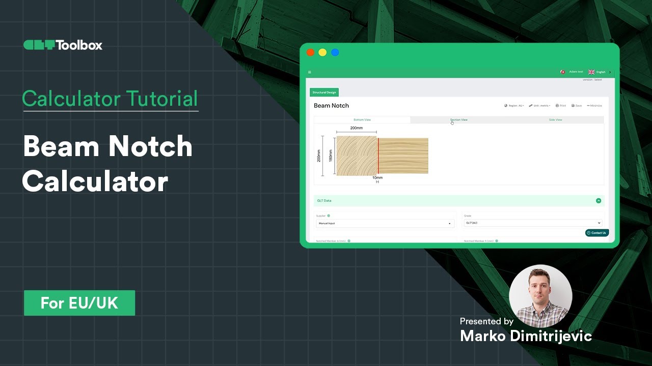
Balknotskalkylator
Design och verifiering av en GLT-balk med skåra enligt EC5 med CLT Toolbox
Den viktigaste frågan: ger det reducerade tvärsnittet tillräcklig kapacitet, eller krävs förstärkning med skruvar?
Här är vad vi behandlade i den här videon:
– Hur man kontrollerar skårans kapacitet med EC5
– När och hur man använder förstärkningsskruvar baserat på ETA-data från leverantörer
– Introduktion till skruvgeometri
– Hur skruvens position, orientering och antal kan optimera konstruktionen
En praktisk guide till säkra och effektiva träförband. Vi skulle gärna höra dina tankar eller erfarenheter av liknande konstruktioner!
Halvvarvskopplingsberäknare
Lär dig hur du använder CLT Toolbox Half-lap-kalkylatorn för att modellera en golv-till-golv-membrananslutning. Vi börjar med att välja CLT-uppläggning, leverantör och överlappningsbredd, och går sedan igenom skillnaden mellan diskreta och kontinuerliga beräkningslägen. Utforska alternativ för skruvleverantörer, skruvfamiljer och ETA-baserad optimering.

Spline-anslutningskalkylator
Lär dig hur du konstruerar en CLT-spline-panel-till-panel-anslutning med hjälp av ingångskrafter från membranberäkningar. Välj CLT-leverantör, splinebredd, densitet och material, med en förklaring av korrekt skruvval och tillgänglighet för att ställa in olika skruvleverantörer, deras skruvfamiljer och skruvtyper. För varje grupp finns utbildningsinnehåll som hjälper dig att välja rätt skruvprodukt. Växla enkelt mellan analysmetoder, inklusive nuvarande och nya Eurocode 5-metoder.
Frequently Asked Questions
Can I use this for official calculations today?
Yes. The default setting is strict EN 1995-1-1:2004 + A2:2014. The prEN 1995 features are clearly marked as “Draft/Future” provisions, allowing you to use them for comparative analysis or internal verification of Mass Timber elements not fully covered by the old code.
How does the calculator handle CLT differently with prEN 1995?How does the calculator handle CLT differently with prEN 1995?
The prEN draft introduces specific embedment strength ($f_{h,k}$) equations for CLT that account for the gaps and orthogonal layers. Using the prEN toggle ensures your screw values are derived from a standardized consensus rather than varying supplier interpretations.
Does this support reinforcing screws?
Yes. A major focus of the Second Generation Eurocode is reinforcement. You can calculate the capacity of fully threaded screws used specifically to prevent splitting (tension perpendicular to grain) in notched beams or around hole penetrations.

 CLT
CLT Dowels
 Skruvar
 GLT
GLT Fästen
 Light-frame