
Timber Concrete Composite (TCC) Design Software for AS1720.1 | Engineering Platform
Launch the free Timber Concrete Composite (TCC) Calculator below & verify your design in seconds!
The New Standard for Australian Mass Timber Engineering
Timber–Concrete Composite (TCC) floor systems are gaining increasing attention as engineers seek solutions that combine the sustainability of timber with the stiffness and mass of concrete. By integrating a concrete slab with timber panels through mechanical connectors, TCC systems can significantly improve structural stiffness, vibration performance, and load-carrying capacity compared to timber-only floors.
Despite these advantages, designing timber–concrete composite floors remains complex. The structural behaviour depends on the interaction between timber, concrete, and the shear connectors that transfer forces between the two materials. This composite interaction must be carefully evaluated to accurately predict bending stiffness, internal force distribution, and long-term performance.
Under the Eurocode framework, TCC systems are typically designed using EN 1992-1-1 – Eurocode 2 (Concrete Structures) together with EN 1995-1-1 – Eurocode 5 (Timber Structures). Because composite timber–concrete floors are not covered by simplified “Deemed-to-Satisfy” provisions, engineers often rely on analytical approaches such as the Gamma Method or Extended Gamma Method to model partial composite action and verify structural capacity, serviceability, and connection performance.
The Australian Engineering Platform for Timber Concrete Composite (TCC) Design
Our platform performs a check for Timber–Concrete Composite (TCC) Design to AS1720. The calculation module include:

Våra partneruppdateringar
Den snabbast växande plattformen för trävaruspecifikationer
Key Timber–Concrete Composite Design (TCC) Design Capabilities
Overview of Timber–Concrete Composite Systems
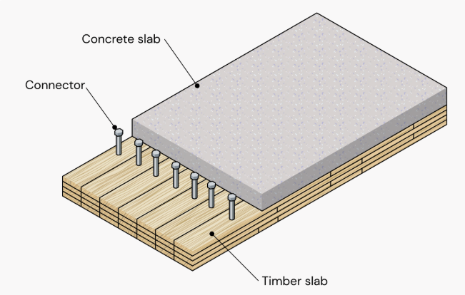
Timber–Concrete Composite (TCC) systems combine timber structural members with a concrete slab connected through mechanical fasteners. The composite interaction between the materials increases stiffness, load capacity, and vibration performance compared to timber-only floor systems.
The SPEC Toolbox Timber–Concrete Composite calculator allows engineers to analyze composite floor systems composed of:
-
CLT timber panels
-
reinforced concrete slab
-
inclined screw connectors
The calculator evaluates:
-
concrete capacity
-
timber capacity
-
connection capacity
-
composite bending behavior
-
deflection performance
-
vibration response
The structural interaction between the timber and concrete layers is modeled using mechanical connectors and composite beam theory, allowing realistic prediction of system behavior.
For the Eurocode region, the calculator uses the following standards:
Design Codes
-
EN 1992-1-1:2004 – Eurocode 2: Design of Concrete Structures
-
EN 1995-1-1:2004 – Eurocode 5: Design of Timber Structures
Loading Code
-
EN 1991:2002 – Eurocode 1: Actions on Structures
These standards define the material models, safety factors, and verification procedures used in the analysis.
Geometry and Components
A timber–concrete composite floor consists of two primary structural components:
-
CLT timber panel
-
concrete slab
The concrete slab resists compressive forces and increases bending stiffness, while the timber panel primarily carries tensile stresses.
The system geometry is defined by:
-
CLT panel layup
-
concrete slab thickness
-
reinforcement parameters
-
connector spacing
-
span length
These parameters determine the composite stiffness and structural performance of the floor system.
The CLT panel is defined using manual layer input, where the user specifies:
-
layer thickness
-
fiber orientation
-
timber grade
-
stacking configuration
This allows modeling of custom CLT configurations.
The concrete layer is defined using:
-
concrete grade
-
concrete thickness
-
cement type
-
relative humidity
These parameters influence the stiffness and long-term behavior of the composite system.
Reinforcement parameters include:
-
reinforcement strength
-
bar diameter
-
reinforcement spacing
These values are used for crack control and reinforcement verification.
Design Methods
Composite behavior between the timber and concrete layers is evaluated using analytical methods that account for connector flexibility.
The calculator supports the following analytical methods:
-
Extended Gamma Method
-
Equivalent Gamma Method
These methods determine the effective bending stiffness of the composite section, considering slip between timber and concrete layers.
Additional design parameters include:
-
composite stiffness factor
-
verification condition (t = 0 and t = ∞)
-
material design factors
These parameters influence the composite structural verification.
Loads
The composite floor is analyzed as a beam system subjected to distributed loads.
Users define:
-
span length
-
support conditions
-
load distribution
The analysis determines:
-
bending stresses
-
shear forces
-
composite section stresses
-
connector shear forces
These values are used for ultimate and serviceability verification.

Vibration Methods
Floor vibration performance is evaluated using available vibration assessment methods.
Available vibration methods:
-
Hamm et al. 2010
-
FPInnovations
-
prEN 1995:2023
Additional vibration parameters include:
-
floor performance level
-
secondary width
-
damping ratio
-
walking frequency
-
floating screed stiffness
-
support condition
These parameters influence the dynamic response of the floor system.

Screw Data
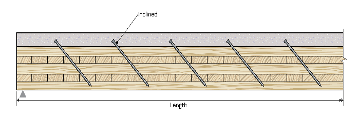
Composite interaction between the timber and concrete layers is achieved using inclined screw connectors.
Users define:
-
fastener type
-
screw orientation (inclined)
-
connector stiffness parameters
Screw properties are defined using manual input, including:
-
screw type
-
tensile strength
-
associated density
-
nominal diameter
-
screw length
-
threaded length
-
inner thread diameter
-
tip length
Connection geometry is defined using:
-
spacing along the beam (a₁)
-
spacing across the beam (a₂)
-
edge distance (a₃)
-
embedment length
-
connector position
These parameters determine the shear transfer capacity between timber and concrete layers.
Design Checks
After the analysis, the calculator provides a complete verification summary.
The following checks are evaluated:
Ultimate Limit State (at t=0 and at t=∞)
-
Concrete capacity
-
Timber capacity
-
Connection design
Serviceability Limit State
-
Avböjning
-
Vibration performance
Each verification includes a utilization ratio and pass/fail indicator, allowing engineers to quickly assess the structural performance of the timber–concrete composite system.
Tutorials
CLT Floor-to-Wall Connection Design

Slab-to-Beam Connection Design
Half-Lap Connection Design
Join us as we break down the Half-Lap joint design, focusing on maintaining structural continuity without external steel plates. Using the Screw Module, we walk through the auto-checking of edge distances and spacing requirements critical for these tight geometric joints.

CLT-väggkalkylator
I den här videon lär du dig steg för steg hur du utformar ett typiskt CLT-väggelement. Vi går igenom hur du väljer CLT-leverantör, använder rätt funktioner, dynamiska bilder och utbildningsinnehåll för att bestämma optimal paneltjocklek och design. Du får också se hur du växlar mellan plattform- och ballongramtyper, tillämpar olika excentricitetsmetoder och lägger till belastningar i planet och utanför planet – vilket ger dig en gedigen förståelse för grunderna i CLT-väggberäkningar och -design.
Massivt trä formar framtiden för hållbart byggande. Med rekordstora träbyggnader som dyker upp över hela världen är det viktigare än någonsin att behärska CLT-design. Kolla in vår CLT Toolbox-app för kraftfulla designverktyg, automatiserade beräkningar och expertinsikter som hjälper dig att effektivisera dina CLT-projekt!

CLT-diafragma-beräkningsverktyg
En komplett guide till hur man ställer in och analyserar membranets beteende i X-riktningen med hjälp av CLT Toolbox. Du definierar skruvtyper för styvhetsberäkningar, ställer in panelgeometri, anslutningstyper och panelbredder. Vi går igenom hur man matar in ULS- och SLS-krafter och förklarar nödvändiga skjuvvärden i planet och lamineringsdata. Videon avslutas med en sammanfattning av böjningsresultat, kraftpåverkan och hållfasthetskontroller enligt Eurokod 5.

CLT-golv Brandkonstruktion
Vi är glada över att kunna lansera den efterlängtade branddesignmodulen för CLT-golv, som nu finns tillgänglig tillsammans med omgivningsdesignkalkylatorn på CLT Toolbox.
Denna handledning går igenom hur den nya modulen fungerar, inklusive vilka standarder som stöds och hur teckendjupet beräknas lager för lager.
Key features include:
- Support for multiple fire models:
– Draft Eurocode 5 (prEN 1995-1-2:2023)
– Austrian National Annex (ÖNORM B EN 1995-1-2:2011)
– Standard Fire Tests (ISO 834 / EN 1363-1) - Flexibility to define protection layers and fire-exposed sides
- Automatic layer-by-layer charring depth calculations over time
- Clear logic for bond-line failure and glue-line degradation
- Full PDF export with all intermediate steps, safety factors and inputs
Byggd för att ge ingenjörer transparens, noggrannhet och snabbhet vid brandkonstruktion av CLT.

CLT-skjuvväggskonstruktion
Vi är glada att kunna meddela att den andra versionen av vår CLT-skjuvväggskalkylator nu är LIVE!
Efter 12 månader av att ha lyssnat på användarnas feedback är vi glada att kunna lansera ett förbättrat och mer robust verktyg för konstruktion av skjuvväggar.
CLT-skjuvväggar har utmärkt styrka i planet och kan fungera som ett pålitligt system för att motstå sidokrafter.
Den andra versionen av kalkylatorn innehåller funktioner som fem avancerade lastöverföringsmetoder – baserade på forskning från Casagrande, Wallner-Novak, Tomasi, Pei och Reynolds. Vi har också lagt till kontroller av lateral deformation och beräkningar av panelstyvhet enligt ProHolz 2014 Guide. Slutligen inkluderar vi också In-plane Design of CLT enligt både Proholz 2014 och FP Innovations 2019.
Vi lägger till beräkningsverktyget för skjuvväggar i gratisversionen under oktober månad. Gå till appen och kolla in det 🙂

CLT-golvdesignkalkylator
Följ med oss när vi utforskar allt från att välja den perfekta CLT-panelen – oavsett om du väljer en leverantörs produkt eller matar in dina egna data manuellt – till att välja rätt nationell bilaga, definiera belastningar och finjustera detaljerna. Den här videon guidar dig genom varje steg, inklusive strukturanalys, styvhetsberäkningar och till och med integrering av kantlimmade lameller i din design.
Vi kommer också att undersöka hur olika vibrationstekniker påverkar din konstruktion och visa hur du kan optimera din design genom att ta hänsyn till betongavjämningens styvhet i planet och påverkan av flexibelt stöd. Dessutom kommer du att kunna följa resultat och formler under hela processen, så att du alltid är uppdaterad.
Nu kör vi igång!

CLT-diafragma-beräkningsverktyg
Kom igång med en heltäckande metod för membrankonstruktion genom att definiera krafter, materialegenskaper och tillämpa Eurocode 5-parametrar. Börja med att definiera de ingående krafter som verkar på membranet i X-riktningen och välj skruvtyper för styvhetsberäkningar. Ställ in membranets geometri och orientering i användarinmatningarna, typ av panelanslutningar och panelbredd med teknisk information från CLT-leverantörer. Ange krafter för både ULS och SLS, med hänsyn till kraftens riktning. Förstå skjuvvärden i planet, erforderliga lamineringsdata och viktiga konstruktionsparametrar för Eurokod 5. Analysera slutligen böjningsresultat, den underliggande teorin, verkande krafter och hållfasthetskontroller för att säkerställa en precis och effektiv konstruktion.

Frequently Asked Questions
Why use timber–concrete composite floors?
Timber–concrete composite floors combine the sustainability of timber with the stiffness and mass of concrete. This improves structural stiffness, vibration performance, and load capacity compared to timber-only floors.
Why are mechanical connectors critical in TCC design?
Mechanical connectors control the shear transfer between the concrete slab and the timber member. Their stiffness and spacing determine how effectively the two materials act together as a composite section.

 Dowels
 CLT
CLT Skruvar
 GLT
GLT Fästen
 Light-frame
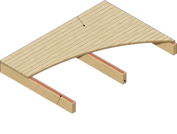 Ribbad däck
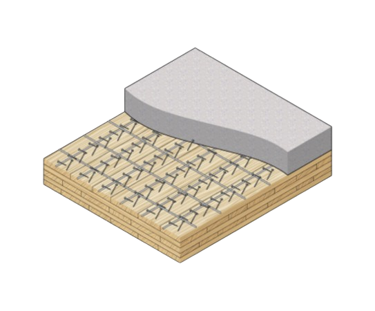 TCC
TCC