
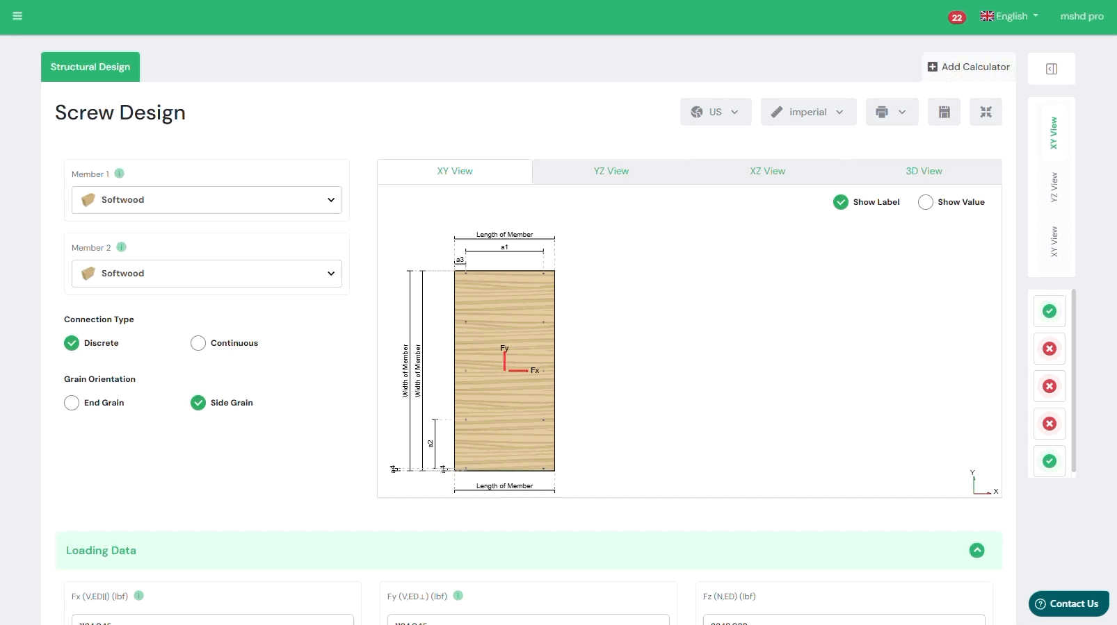
Wood Screw Design for NDS
Design screws to NDS 2018 & Supplier ICC/ESRs. Use the free web calculator below to automate your design in seconds!
The Consolidated Screw Engineering Platform
The NDS 2018 Screw Calculator is a sophisticated tool designed for structural engineers to perform comprehensive lateral and withdrawal design calculations for dowel-type fasteners. This powerful calculator helps you analyze and optimize connections in Sawn Lumber, Glulam, and Mass Timber (CLT) with precision and efficiency.
Caratteristiche principali:

Aggiornamenti dei nostri partner
La piattaforma in più rapida crescita per le specifiche del legname
About Screw Design
Stop Calculating Yield Modes by Hand
The days of manually iterating through the six Yield Limit Equations (NDS Table 11.3.1A) are over. The SPEC Toolbox calculator handles the complex interaction between fastener bending yield strength (Fyb ) and the dowel bearing strength (Fe ) of wood members instantly.
We solve for all failure modes simultaneously to identify the controlling Reference Lateral Design Value (Z):
- Mode Im & Is : Wood bearing failure in the main or side member.
- Mode II: Fastener rotation failure.
- Mode IIIm & IIIs : Fastener plastic hinge formation (single curvature).
- Mode IV: Fastener plastic hinge formation (double curvature).
Our engine automatically adjusts Fe based on specific gravity (G) and the angle of load to grain, ensuring you get accurate results for both Parallel to Grain and Perpendicular to Grain loading.
Comprehensive Withdrawal & Head Pull-Through Design
Lateral capacity is only half the equation. Our calculator provides a complete analysis of tension and withdrawal forces.
Withdrawal Design Value (W): We calculate capacity per inch of thread penetration based on the specific gravity of the main member (W=1800G3/2D3/4 for lag screws).
- Head Pull-Through (WH ): For thin side members, the calculator checks the resistance of the screw head against the wood fiber, critical for ensuring ductile failure modes in connections.
- End Grain Adjustments: The tool automatically applies the End Grain Factor (Ceg ) when you specify withdrawal from the end of a member, preventing unsafe design assumptions.
Advanced Support for Mass Timber & CLT
Standard “wood screw” calculators often fail when applied to modern Mass Timber elements. SPEC Toolbox is built for the Cross-Laminated Timber (CLT) era.
Dowel-Type Fasteners in CLT (PRG-320)
Designing connections in CLT requires adherence to specific product standards like ANSI/APA PRG-320. Our calculator allows you to:
- Input custom CLT layups or select from standard grades (E1, V1, etc.).
- Differentiate between Narrow Face and Wide Face connections.
- Account for gaps between laminations which can reduce fastener penetration depth.
Inclined Screw Technology
Maximize connection stiffness and capacity by utilizing inclined screws. By installing fully threaded screws at an angle (typically 45°), you can engage the axial capacity of the screw rather than relying solely on shear. This is ideal for Timber-Concrete Composite (TCC) systems and high-load girder connections.
Automatic Adjustment Factors (NDS Table 10.3.1)
The Reference Design Value (Z or W) is rarely the final number. We automate the application of all applicable Adjustment Factors to determine the Adjusted Design Value (Z′ or W′):
- Load Duration Factor (CD ): Toggle instantly between occupancy (1.0), snow (1.15), construction (1.25), and wind/seismic (1.6) load cases.
- Wet Service Factor (CM ): Adjusts capacity for exterior exposure or high-moisture environments.
- Group Action Factor (Cg ): Automatically reduces capacity per fastener based on the number of screws in a row (n) and spacing, as required by NDS 11.3.6.
- Geometry Factor (CΔ ): Ensures reductions are applied if end distance or spacing falls below the full-capacity minimums.
Frequently Asked Questions
Does this calculator support ASD and LRFD?
Yes. For the US market, you can toggle between Allowable Stress Design (ASD) and Load and Resistance Factor Design (LRFD). The calculator automatically applies the Format Conversion Factor (KF ) and Resistance Factor (ϕ) for LRFD checks.
Can I use this for Canadian projects (CSA O86)?
Absolutely. Simply switch the standard toggle to CSA O86-19. The interface updates to calculate Factored Lateral Resistance (Nr ) and Withdrawal Resistance (Pr ), replacing NDS terms with Canadian Limit States Design (LSD) terminology.

 Viti
Viti GLT
GLT Dowels
 CLT
CLT