
Dowel & Bolt Connection Design Software for NDS 2024
Design complex timber connections to NDS 2024. Analyze Shear, Axial, and Moment actions on multi-bolt groups with our new dynamic visual engine.
Advanced Engineering Software for Complex Timber Connections
For years, American engineers have been restricted to the simplified “Reference Design Value (“Z”)” tables in the NDS, which struggle to handle complex geometries or combined loading.
The SPEC Toolbox Dowel & Bolt Module changes the game. It runs the full Yield Limit Equations (Modes Im through “IV”) in real-time. Whether you are designing a high-load truss heel connection or a moment-resisting beam splice, this tool provides the rigorous analysis required by NDS, solving for combined actions and group effects instantly.
What This Calculator Does
This module utilizes a dynamic visual engine to optimize dowels, bolts, and steel plates. It handles the complexity of “The Black Box” of connection design:

Key Dowel & Bolt Connection Design Capabilities
Overview of Dowel-Type Timber Connections
Dowel-type fasteners such as bolts and steel dowels are among the most widely used connection systems in structural timber engineering. These fasteners transfer forces between timber members through bearing stresses in the wood and bending of the fastener.
SPEC Toolbox provides an advanced calculator for the design and verification of dowel-type connections in timber elements with steel plates. The tool evaluates the interaction between timber members, steel plates, and fasteners, enabling engineers to verify connection capacity under combined loading conditions.
For the United States region, the calculator supports the following design standard:
• AWC NDS:2024 – National Design Specification for Wood Construction
The design methodology follows the connection design provisions defined in the American Wood Council National Design Specification (NDS) for dowel-type fasteners.
The calculator supports bolts and steel dowels installed in timber members with steel side plates and allows flexible configuration of plate positions, fastener layouts, and loading conditions.
Applied Forces and Connection Configuration
The structural behavior of a dowel-type connection is governed by the forces acting on the joint. The calculator allows engineers to define the primary load components transferred through the connection.
The following loads can be applied:
Axial Tension Force (Fx)
Force acting parallel to the connection axis that produces tension in the timber and fastener group.
Shear Force (Fz)
Force acting perpendicular to the fastener axis and transferred through bearing between the timber and the fasteners.
Bending Moment (My)
Moment applied to the connection that introduces additional force redistribution within the fastener group.
Engineers can also define the connection configuration, determining whether the connection acts as a primary structural element or as part of a larger load transfer system.
Yield Model Analysis for Dowel-Type Fasteners
The calculator evaluates dowel-type connections using the Yield Limit Equations (YLE) defined in the AWC NDS standard.
This analytical approach considers the interaction between:
-
timber bearing strength
-
fastener bending yield strength
-
steel plate stiffness
-
load distribution within the fastener group
The Yield Limit Equation method evaluates several potential failure mechanisms, including:
-
timber bearing failure
-
fastener yielding
-
combined timber-fastener plastic mechanisms
These equations are used to determine the governing connection capacity under shear loading.
The design procedure applies the appropriate adjustment factors and safety factors defined in the AWC NDS design provisions.
Design Parameters
AWC NDS Design Factors
The calculator includes design parameters defined in AWC NDS:2024 that modify the connection resistance according to environmental conditions and structural configuration.
Engineers can define the following design parameters:
-
Design Method
-
Allowable Stress Design (ASD)
-
Load and Resistance Factor Design (LRFD)
-
-
Load Duration
-
Moisture Content at Time of Fabrication
-
Moisture Service Content
-
Temperature Condition
-
Temperature Factor (Ct)
-
Load Duration Factor (CD)
-
Time Effect Factor (λ)
-
Repetitive Member Factor (Cr)
-
Geometry Factor (CΔ)
-
Edge Bonded Factor (CEB)
-
Wet Service Factor (CM)
-
Shear Reduction Factor (Cvr)
These factors modify the connection resistance according to the conditions defined by the NDS design standard.
Timber Member Configuration
The timber member forms the primary structural component of the connection. Its geometry and material properties significantly influence the connection capacity.
Engineers can define:
-
timber member thickness
-
timber material properties
-
steel plate placement within the timber section
-
plate arrangement (uniform or non-uniform placement)
These parameters determine the load transfer mechanism and influence:
-
fastener spacing requirements
-
splitting resistance
-
overall joint behavior
Steel Plate Properties
Steel plates are frequently used in timber connections to improve load distribution and increase joint capacity.
The calculator allows engineers to define the mechanical and geometric properties of the steel plate, including:
-
steel plate grade (e.g., ASTM A36 carbon steel)
-
plate thickness
-
plate depth
-
edge distances
-
end distances
Material properties such as yield strength and ultimate strength are used to evaluate the structural resistance of the steel plate.
The system verifies the plate against potential failure mechanisms including:
-
plate bending
-
bearing capacity
-
shear capacity
-
block tearing resistance
-
tension capacity
-
buckling strength
This ensures that the steel component of the connection remains structurally adequate.
Fastener Type and Mechanical Properties
Fasteners are the primary load-transferring elements within dowel-type timber connections.
The calculator supports the design of:
• Bolts
• Steel dowels
Engineers can define the fastener characteristics, including:
-
fastener diameter
-
fastener grade (e.g., ASTM A307 Grade A)
-
number of fasteners per row
-
number of rows
-
bolt distribution pattern
-
installation angle
These parameters directly influence the fastener capacity, load distribution, and governing connection failure mode.
Spacing and Edge Distance Requirements
Proper fastener spacing and edge distances are essential to prevent brittle timber failure modes such as splitting or block shear.
The calculator allows engineers to define:
-
spacing along the grain (a₁)
-
spacing across the grain (a₂)
-
loaded end distance (aₜ)
-
unloaded edge distance (a_c)
-
edge distances
Engineers can either define these values manually or apply minimum spacing requirements according to AWC NDS provisions.
These geometric constraints ensure proper stress distribution and sufficient timber strength around the fasteners.
Automated Connection Capacity Checks
After defining the geometry, materials, and loads, the calculator performs a complete structural verification of the connection.
The following checks are automatically evaluated.
Geometric Verification
Ensures that spacing, edge distances, and layout requirements satisfy the AWC NDS geometric provisions.
Timber Member and Fastener Checks
The connection is evaluated for multiple potential timber and fastener failure modes, including:
-
Fastener yielding resistance (N₀,y)
-
Row shear resistance (N₀,rs)
-
Group tear-out resistance (N₀,gt)
-
Net tension resistance of the timber member (N₀,t)
Results and Output Summary
The results are presented in a clear output summary dashboard, allowing engineers to quickly identify governing failure mechanisms and verify whether the connection satisfies the design requirements.
The summary view highlights:
-
geometric verification status
-
timber member verification
-
fastener resistance checks
-
governing failure mechanisms
This allows engineers to quickly confirm whether the connection satisfies the AWC NDS design requirements.
Frequently Asked Questions
Does it handle LRFD?
Yes. While the default output is often ASD (Allowable Stress Design), you can toggle the settings to perform an LRFD analysis, which applies the Format Conversion Factor ($K_F$) and Resistance Factor ($\phi$).
What about 1/4" Steel plates?
The tool automatically detects if a metal side plate is used and switches the Yield Mode equations to the “Metal Side Member” variations (NDS Table 11.3.1B).

 Viti
Viti GLT
GLT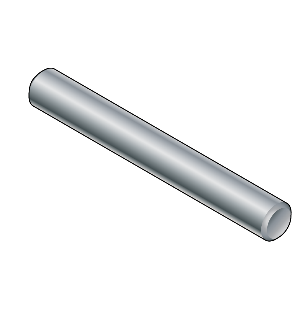 Dowels
 CLT
CLT