
Timber Stud Wall Design for Eurocode 5
Design light-frame wall studs to Eurocode 5. Analyze external C24 timber walls under combined axial roof loads and lateral wind pressure.
The Core of Timber Frame Construction
Timber frame is the dominant method for low-rise residential construction across the UK and Europe. Whether you are designing a load-bearing external wall or an internal partition, the vertical studs are the “spine” of the structure.
The SPEC Toolbox Stud Wall Calculator automates the complex stability checks of Eurocode 5. It allows you to verify standard solid timber sections (e.g., $140 \times 38$, $89 \times 38$ CLS) against buckling and wind deflection, replacing tedious manual interaction calculations.
What This Calculator Does
This tool performs a rigorous analysis of a vertical timber stud as a “Beam-Column” element. It verifies:

Key Stud Design Capabilities
Overview of Light-Frame Timber Stud Design
Light-frame timber construction is one of the most widely used structural systems for residential and low-rise buildings. In this system, vertical timber members known as studs transfer loads from floors and roofs down to the foundation while being stabilized by horizontal members and structural sheathing.
SPEC Toolbox provides a dedicated Stud Design calculator that allows engineers to analyze the structural performance of timber studs within light-frame walls. The calculator evaluates axial compression, bending effects, buckling behavior, and stability conditions in accordance with European timber design standards.
The tool supports solid timber studs used in light-frame wall assemblies, allowing engineers to define geometric properties, spacing, loading conditions, and structural parameters to verify member performance under combined loads.
For the European region, the calculator supports the following design standard:
• EN 1995-1-1:2004 (Eurocode 5)
Eurocode 5 defines the design procedures for timber structures, including compression members, stability checks, and load combinations for structural verification.
Timber Stud Properties
The structural capacity of a light-frame wall depends primarily on the geometry and material properties of the timber studs.
The calculator allows engineers to define the following parameters:
-
Timber grade (e.g., C16, C24)
-
Stud width (b)
-
Stud depth (d)
-
Stud spacing
These parameters determine the cross-sectional resistance and slenderness of the stud.
Stud spacing is particularly important because it determines the load tributary area transferred from floors and roofs to the individual stud members.
Wall Type
The wall assembly may be defined as:
• Discrete wall
• Continuous wall
A continuous wall configuration assumes the studs act as part of a continuous wall system with load redistribution between members. A discrete configuration treats each stud as an individual structural element.
Sheathing and Bracing Conditions
Sheathing materials such as OSB or plywood can significantly influence the stability and buckling behavior of the studs.
The calculator allows engineers to define:
-
Whether sheathing is present
-
Whether sheathing provides lateral support
-
Whether braced battens are installed
These parameters influence the effective buckling length of the stud and the overall stability of the wall system.
European Timber Design Standard
The calculator performs structural verification according to Eurocode 5 (EN 1995-1-1:2004).
Engineers can define additional parameters related to national design provisions.
National Annex
Eurocode 5 allows countries to define national parameters through a National Annex (NDP – Nationally Determined Parameters).
The calculator allows engineers to:
-
activate the National Annex
-
select the country-specific NDP code
For example:
• Austria – ÖNORM B
These parameters adjust partial safety factors and other design values according to national regulations.
Load Cases and Combinations
The structural performance of a stud depends on the loads acting on the wall system. The calculator allows engineers to define the primary load components according to Eurocode load combination rules.
The following load types can be applied:
• Permanent load (gk)
• Imposed load (qk)
• Wind load (wk)
• Snow load (s)
These loads are combined using Eurocode load combinations defined in EN 1990 and EN 1991.
Load Combination Selection
Engineers can select the design combination method used for structural verification.
Parameters include:
-
Load combinations
-
Loading code (EN 1991:2002)
-
Consequence class
-
Design equation
These settings determine how loads are factored and combined for ultimate limit state verification.
Environmental and Service Conditions
The calculator also includes parameters that influence material performance under environmental conditions.
Engineers can define:
-
Service class (SC1, SC2, etc.)
-
Snow load category
-
Imposed load category
These parameters adjust design factors and material properties according to the Eurocode provisions.
Axial Loads
Vertical loads acting on the wall are applied as axial compression loads on the studs.
The calculator allows engineers to define the distributed loads transferred to each stud from the structure above:
-
Permanent load (gk)
-
Imposed load (qk)
-
Wind load (wk)
-
Snow load (s)
These loads represent the tributary load carried by the stud.
Lateral Loads
Wind loads acting on the wall generate lateral pressure that induces bending in the studs.
The calculator allows engineers to define:
• Wind load (Wn-y) acting perpendicular to the wall surface.
This lateral load produces bending stresses in the stud that must be combined with axial compression during design verification.
Eurocode Stability Parameters
Additional parameters influence the stability verification of the stud.
System Factor – ksys
The system factor accounts for load sharing between multiple members in a repetitive structural system.
Critical Buckling Calculation
The calculator allows engineers to determine whether the critical buckling coefficient (kcrit) should be evaluated.
Loaded Edge Condition
The position of the loaded edge relative to the stud cross-section influences bending resistance.
The calculator allows engineers to select:
-
Compression edge
-
Center
-
Tension edge
These parameters affect the evaluation of lateral torsional stability.
Automated Stud Capacity Checks
After defining the geometry, materials, and loading conditions, the calculator performs a complete structural verification of the stud.
The following checks are automatically evaluated:
Bending Design
Verifies that the stud has sufficient bending capacity under lateral loads.
Compression Check
Evaluates the axial compression resistance of the stud.
Strength Check
Ensures that the combined stresses remain within allowable design limits.
Buckling Verification
Checks the global buckling resistance of the stud under axial compression.
Lateral Torsional Stability
Evaluates the stability of the stud against lateral torsional buckling, particularly when bending is present.
Output Summary
The results are presented in a clear summary dashboard that allows engineers to quickly assess structural performance.
Each verification check is displayed with a pass/fail indicator, including:
-
Bending design utilization
-
Compression utilization
-
Strength interaction check
-
Buckling verification
-
Lateral torsional stability
This allows engineers to quickly identify governing failure mechanisms and verify that the stud satisfies all Eurocode design requirements.
Tutorials
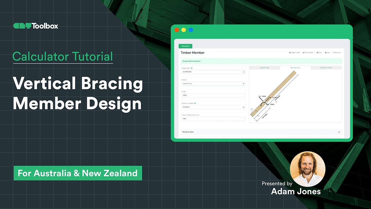
Diseño de elementos de refuerzo verticales
Aprenda a utilizar la calculadora de miembros de CLT Toolbox para diseñar un refuerzo diagonal vertical. Le guiaremos a través de la importación de resultados de análisis desde herramientas externas, la identificación de las fuerzas máximas de tensión y compresión, y la selección de los datos de entrada adecuados: calidades, secciones, especificaciones del código y fuerzas. Además, desglosaremos los resultados, cubriendo las propiedades de los materiales y todas las comprobaciones clave del diseño. ¡CLT Toolbox está aquí para ser su socio en el diseño de proyectos de madera!
Frequently Asked Questions
Can I design "Double Studs"?
Yes. You can select “2x” or “3x” member configurations (e.g., at window openings). The calculator adjusts the cross-sectional area and moment of inertia to represent the built-up column.
Does it check Fire Resistance?
This module checks Structural (Cold) Design. For fire (e.g., REI 30), use our Char Rate Calculator to check the residual section capacity, or specify a “Fire Check” stud size (e.g., adding 20mm to the width).
What about racking/bracing?
This tool designs the vertical load-bearing studs. It does not calculate the racking resistance of the plywood shear wall itself. We have an upcoming light-frame shear wall calculator that solves for this.

 CLT
CLT Dowels
 Tornillos
 GLT
GLT Soportes
 Light-frame