
Wood Screw Design Software to Eurocode 5
Use our free web calculator & learn everything you need to know about screw design to Eurocode 5! Second Generation Eurocodes included.
A Timber Engineering Platform Automating Your Screw Design
The Eurocode 5 Screw Calculator is the only engineering tool built for the transition to the Second Generation Eurocode. It calculates the Design Load-Carrying Capacity (Fv,Rd) and Axial Withdrawal Capacity (Fax,Rd) of fasteners while integrating the expanded scope of prEN 1995-1-1 regarding Cross-Laminated Timber (CLT) and brittle failure modes.
Características principales:

Actualizaciones de nuestros socios
La plataforma de más rápido crecimiento para la especificación de madera
Key Screw Design Module Capabilities
Overview of Structural Screw Connections
Self-tapping screws are widely used in modern timber engineering for transferring axial and shear forces between structural elements. These fasteners provide high load-bearing capacity, simple installation, and versatile connection configurations for timber-to-timber and timber-to-steel joints.
The SPEC Toolbox Screw Design module allows engineers to evaluate screw connections in a wide range of timber structures using manufacturer-specific fastener data. The calculator integrates real screw geometries and product libraries from leading suppliers, enabling accurate modelling of screw behaviour and load transfer.
The tool supports different timber materials and connection types commonly used in timber construction.
Supported member materials include:
-
Softwood
-
Hardwood
-
Glulam (GLT)
-
Cross-Laminated Timber (CLT)
-
Laminated Veneer Lumber (LVL)
-
Plywood
-
Steel plates for timber-to-steel connections
This flexibility allows engineers to evaluate connections in both traditional timber structures and modern engineered timber systems.
Interactive Connection Model
To assist with connection configuration, the calculator provides an interactive 3D visualization of the screw arrangement and connected members.
The model shows:
-
screw orientation
-
load directions
-
member geometry
-
fastener placement
Users can rotate and inspect the connection to clearly understand the load transfer mechanism and screw positioning.
This visual feedback helps engineers verify the geometry of the connection before performing structural verification.
Primary and Secondary Member Definition
The calculator allows engineers to define the structural members involved in the connection.
Two members can be configured:
-
Member 1 – primary structural element
-
Member 2 – secondary element or connected member
For each member, the following properties can be defined:
-
member material type
-
member dimensions
-
characteristic timber density (ρk)
-
mean density (ρmean)
The density values are used to calculate the embedment strength of the timber and therefore influence the resistance of the screw connection.
Additionally, the grain orientation relative to the screw can be defined to correctly represent load transfer behaviour in the timber.
Applied Forces
The screw connection may be subjected to axial and shear forces acting in multiple directions.
The calculator allows engineers to define the applied loads acting on the connection, including:
-
Fx – shear force in the x-direction
-
Fy – shear force in the y-direction
-
Fz – axial force acting along the screw axis
These load components represent the design actions acting on the connection according to the selected design standard.
The combined shear force is automatically calculated and used for connection verification.
The applied loads are visualized in the connection model to clearly illustrate their direction and point of application.
Supplier and Product Library
The calculator integrates screw data from recognized manufacturers, allowing engineers to select fasteners directly from supplier product libraries.
Users can define:
-
screw supplier
-
screw family
-
specific screw type
Each screw type includes predefined mechanical properties such as:
-
diameter
-
thread configuration
-
strength properties
-
withdrawal resistance parameters
This integration ensures that the design calculations are based on realistic fastener properties and certified manufacturer data.
Screw Type and Thread Configuration
Different screw configurations can be selected depending on the connection requirements.
Available options include:
-
Partially threaded screws
-
Fully threaded screws
Thread configuration affects the load transfer mechanism and determines whether the screw primarily resists shear forces, axial forces, or combined loading.
The calculator also supports smart screw length selection, helping engineers choose appropriate fastener lengths based on the connection geometry.
Supported Design Methods
Screw connections are evaluated according to Eurocode 5 design provisions for timber connections.
The calculator currently supports three design methodologies:
-
EN 1995-1-1:2004 (Eurocode 5)
Standard design approach for timber connections using dowel-type fasteners. -
prEN 1995:2023
The upcoming revision of Eurocode 5, introducing updated design provisions and calculation models. -
EN 1995-1-1:2004 (Supplier ETA)
Design approach based on manufacturer-specific European Technical Assessment (ETA) values for proprietary fasteners.
These design methods allow engineers to evaluate screw performance according to either general Eurocode rules or manufacturer-certified design data.
Screw Arrangement and Spacing
The geometric arrangement of screws strongly influences the resistance and failure modes of timber connections.
The calculator allows engineers to configure screw placement using two approaches:
Manual Arrangement
Engineers can manually define the screw layout, including:
-
screw spacing
-
edge distances
-
number of screws along different directions
Minimum Distance and Spacing Rules
Alternatively, the calculator can automatically apply Eurocode minimum spacing requirements, ensuring that screw placement satisfies geometric design rules.
Parameters considered include:
-
spacing parallel to grain
-
spacing perpendicular to grain
-
edge distances
-
end distances
-
fastener positioning relative to member geometry
These geometric checks ensure that brittle timber failure modes such as splitting are avoided.
Connection Capacity Checks
After defining the screw configuration, timber properties, and applied loads, the calculator performs structural verification of the connection.
The output summary includes the following checks:
Geometry Check
This verification ensures that screw spacing and edge distances satisfy Eurocode geometric requirements for timber connections.
Shear Capacity
The shear resistance of the screw connection is evaluated according to Eurocode dowel-type fastener models.
Axial Capacity
The axial resistance of the screw is evaluated based on withdrawal resistance and fastener properties.
Combined Actions
When axial and shear forces act simultaneously, the calculator verifies the combined loading condition to ensure the connection capacity is not exceeded.
Slip Modulus
The module also provides the slip modulus of the screw connection, representing the stiffness of the fastener under load. This parameter is important for structural modelling and deformation analysis.
Tutorials
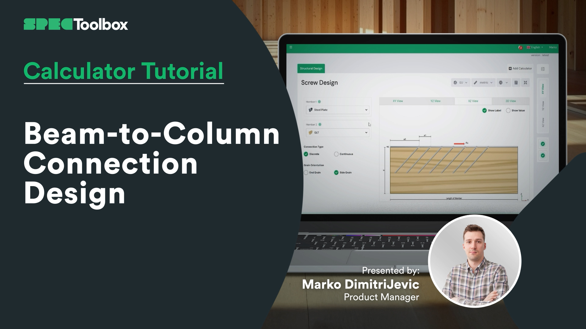
Beam-to-Column Connection Design
Beam-to-Column Connection Tackle the complexity of Beam-to-Column joints in this focused tutorial. We demonstrate how to replace complex bespoke steelwork with smart screw arrangements. Using the Screw Module, we verify the capacity of inclined screw groups to handle significant shear loads directly at the support interface.
Key Screw Benefits:
Crossed-Screw Configurations: Shows how arranging screws in crossed pairs (X-formation) significantly boosts stiffness.
Ductility & Safety: detailed look at how modern structural screws provide necessary ductility for safe, predictable failure modes.
CLT Floor-to-Wall Connection Design

Slab-to-Beam Connection Design

Half-Lap Connection Design
Join us as we break down the Half-Lap joint design, focusing on maintaining structural continuity without external steel plates. Using the Screw Module, we walk through the auto-checking of edge distances and spacing requirements critical for these tight geometric joints.

Tornillos: Madera con carga lateral a madera con carga lateral en el extremo del grano.
Nos complace presentar el módulo de carga lateral entre extremos de madera, una potente herramienta para ingenieros que diseñan uniones con tornillos sometidos a cargas laterales. Esta calculadora especializada garantiza precisión y flexibilidad en los diseños de uniones de madera.
Características principales:
• Códigos de diseño: Compatible con tres códigos de diseño para tornillos con carga lateral: EN 1995:2004, AS 1720:2010 y prEN 1995:2023.
• Entrada de proveedores: Introduzca tornillos de los principales proveedores, como Rothoblass, Eurotec, Sihga, Spax y Simpson's Strong Tie.
• Entrada manual: Permite la introducción manual de los parámetros de los tornillos, incluidas las dimensiones y las propiedades de los materiales.
• Cálculos flexibles: Realiza cálculos basados en el documento ETA o el código de diseño del proveedor seleccionado.
• Diagramas dinámicos: Diagramas interactivos que se actualizan en función de los datos introducidos, visualizando las trayectorias de carga y el rendimiento de los tornillos.
• Resúmenes completos: Resúmenes detallados con comprobaciones geométricas y utilización de la capacidad de corte, que proporcionan datos fiables para las decisiones de diseño.
• Uniones de testa: Diseñadas específicamente para calcular uniones de madera con tornillos fijados en la dirección de la testa.
Esta calculadora especializada ayuda a los ingenieros a garantizar uniones de madera resistentes, fiables y precisas bajo cargas laterales.

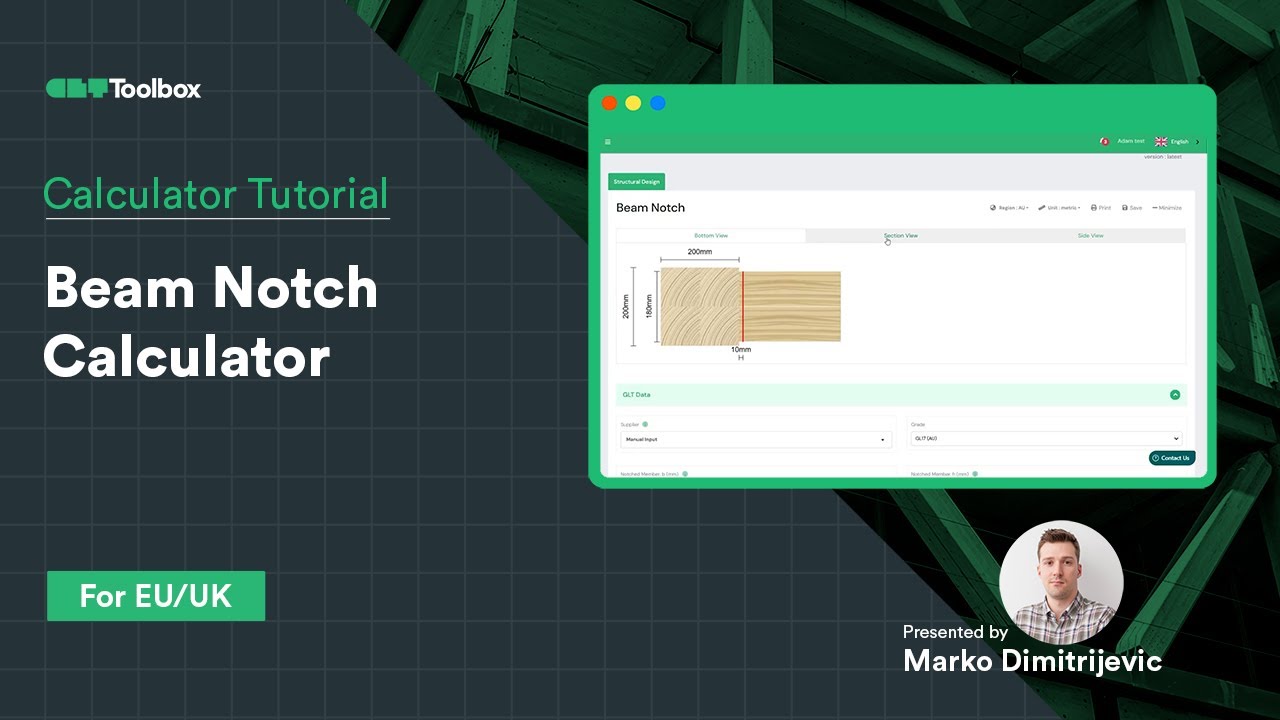
Calculadora de muescas en vigas
Diseño y verificación de una muesca en una viga GLT según EC5 con CLT Toolbox
La pregunta clave: ¿la sección transversal reducida proporciona suficiente capacidad o es necesario reforzarla con tornillos?
Esto es lo que hemos tratado en este vídeo:
– Cómo comprobar la capacidad de la muesca utilizando EC5
– Cuándo y cómo utilizar tornillos de refuerzo basándose en los datos ETA de los proveedores
– Introducción a las entradas de geometría de los tornillos
– Cómo la posición, la orientación y la cantidad de tornillos pueden optimizar el diseño
Una guía práctica para lograr conexiones de madera seguras y eficientes. ¡Nos encantaría conocer tu opinión o tus experiencias con diseños similares!
Calculadora de conexión de media vuelta
Aprenda a utilizar la calculadora de solapas medias de CLT Toolbox para modelar una conexión de diafragma entre pisos. Comenzamos seleccionando la disposición de CLT, el proveedor y el ancho de solapa, y luego repasamos la diferencia entre los modos de cálculo discreto y continuo. Explore las opciones de proveedores de tornillos, familias de tornillos y optimización basada en ETA.

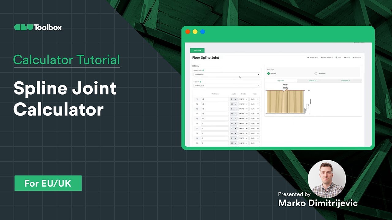
Calculadora de conexión de splines
Aprenda a diseñar una conexión entre paneles de madera contralaminada (CLT) mediante fuerzas de entrada procedentes de cálculos de diafragmas. Seleccione el proveedor de CLT, el ancho, la densidad y el material de la lengüeta, con una explicación sobre la selección adecuada de tornillos y la disponibilidad para configurar diferentes proveedores de tornillos, sus familias de tornillos y tipos de tornillos. Para cada grupo, hay contenido educativo que ayuda a seleccionar el producto de tornillos adecuado. Cambie fácilmente entre métodos analíticos, incluidos los enfoques actuales y los nuevos del Eurocódigo 5.
Frequently Asked Questions
Can I use this for official calculations today?
Yes. The default setting is strict EN 1995-1-1:2004 + A2:2014. The prEN 1995 features are clearly marked as “Draft/Future” provisions, allowing you to use them for comparative analysis or internal verification of Mass Timber elements not fully covered by the old code.
How does the calculator handle CLT differently with prEN 1995?How does the calculator handle CLT differently with prEN 1995?
The prEN draft introduces specific embedment strength ($f_{h,k}$) equations for CLT that account for the gaps and orthogonal layers. Using the prEN toggle ensures your screw values are derived from a standardized consensus rather than varying supplier interpretations.
Does this support reinforcing screws?
Yes. A major focus of the Second Generation Eurocode is reinforcement. You can calculate the capacity of fully threaded screws used specifically to prevent splitting (tension perpendicular to grain) in notched beams or around hole penetrations.

 CLT
CLT Dowels
 Tornillos
 GLT
GLT Soportes
 Light-frame