
Wood Screw Design Software for CSAO86:2024
The latest engineering software to design screws for the latest Canadian standards.
Canadian Screw Engineering Platform
The CSA O86 Screw Calculator is a sophisticated engineering tool designed to calculate the Factored Lateral (Nr ) and Withdrawal (Pr ) resistance of dowel-type fasteners. This tool helps structural engineers optimize connections in Canadian Lumber, Glulam, and Mass Timber (CLT) with strict adherence to the CSA O86-19 standard.
Características principales:

Actualizaciones de nuestros socios
La plataforma de más rápido crecimiento para la especificación de madera
Key Screw Design Module Capabilities
Overview of Structural Screw Connections
Self-tapping screws are widely used in timber engineering to transfer axial and shear forces between structural elements. These fasteners provide high load-bearing capacity, efficient installation, and flexible connection configurations for timber-to-timber and timber-to-steel joints.
The SPEC Toolbox Screw Design module allows engineers to evaluate screw connections using the CSA O86 Timber Engineering Design standard, together with manufacturer-specific fastener data.
The calculator integrates structural design provisions from CSA O86 and enables engineers to model screw connections using realistic geometry, material properties, and loading conditions.
The tool supports several timber and engineered wood materials commonly used in Canadian timber construction.
Supported materials include:
-
Softwood
-
Hardwood
-
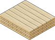
Glulam (GLT)
-
Cross-Laminated Timber (CLT)
-
Laminated Veneer Lumber (LVL)
-
Plywood
-
Steel plates for timber-to-steel connections
This allows engineers to evaluate screw connections in both conventional wood structures and modern mass timber systems.
Interactive Connection Model
The calculator provides an interactive 3D visualization of the screw connection to support intuitive connection configuration.
The model displays:
-
member geometry
-
screw orientation
-
screw placement
-
applied forces
Users can rotate and inspect the connection model to verify the geometry and load directions before performing structural verification.
This visual feedback helps ensure that the connection configuration accurately reflects the intended structural scenario.
Primary and Secondary Member Definition
The screw connection is defined using two structural members:
-
Member 1 – primary structural element
-
Member 2 – secondary or connected element
For each member, the following parameters can be defined:
-
member material type
-
member dimensions
-
relative density (G)
-
mechanical properties
These parameters influence the embedment strength of the timber and therefore affect the resistance of the screw connection.
The calculator also allows engineers to define the grain orientation relative to the screw, which influences load transfer behaviour and connection capacity.
Applied Forces
Screw connections may be subjected to axial and shear forces acting in multiple directions.
The calculator allows engineers to define the loads acting on the connection:
-
Fx – shear force in the x-direction
-
Fy – shear force in the y-direction
-
Fz – axial force acting along the screw axis
The combined shear force V is automatically calculated from the applied shear components.
The loads are visualized within the connection model, clearly indicating the magnitude and direction of the applied forces.
Supplier and Product Library
The Screw Design module allows engineers to define screw properties either through supplier data or manual input.
Users can define the following fastener parameters:
-
Screw type
-
Nominal diameter
-
Shank diameter
-
Root diameter
-
Threaded length
-
Total screw length
-
Head diameter
-
Tip length
-
Tensile strength
-
Fastener yield strength (Fyb)
These parameters define the mechanical behaviour of the fastener and are used to calculate the connection resistance according to CSA O86 provisions.
Screw Type and Thread Configuration
Different screw configurations can be selected depending on the structural application.
Available options include:
-
Partially threaded screws
-
Fully threaded screws
The thread configuration influences how forces are transferred between the connected members and determines whether the fastener primarily resists:
-
axial tension
-
shear forces
-
combined loading conditions
The calculator also supports smart screw length selection, helping engineers select appropriate fastener lengths based on connection geometry.
Supported Design Methods
Screw connections in the Canadian design environment are evaluated according to the CSA O86 Timber Engineering Design Standard.
The calculator currently supports the following design methods:
-
CSA O86:2019
-
CSA O86:2024
Both design methods follow the limit states design approach defined in the Canadian timber design code.
The analytical procedure evaluates the resistance of the connection based on:
-
timber embedment strength
-
fastener yielding behaviour
-
screw withdrawal resistance
-
group effects and brittle failure modes
The selected design method determines the equations and resistance factors applied during the connection verification.
Screw Arrangement and Spacing
The geometric arrangement of screws significantly influences the resistance and failure modes of timber connections.
The calculator allows engineers to configure screw placement using two approaches.
Manual Arrangement
Engineers can manually define:
-
number of screws
-
spacing between screws
-
edge distances
-
end distances
Minimum Distance and Spacing Rules
Alternatively, the calculator can automatically apply minimum spacing and edge distance requirements according to CSA O86 provisions.
These geometric requirements help prevent brittle timber failure modes such as splitting and tear-out.
The parameters evaluated include:
-
spacing between screws
-
spacing between rows
-
edge distances
-
end distances
-
screw position relative to the member face
Connection Capacity Checks
After defining the connection geometry, timber properties, fastener properties, and applied loads, the calculator performs structural verification according to CSA O86 provisions.
The output summary includes the following checks.
Brittle Failure
This verification evaluates brittle timber failure modes around the fasteners, including:
-
Row shear resistance
-
Net tension resistance
-
Group tear-out resistance
-
Splitting resistance
These checks ensure that the timber surrounding the screws can safely transfer the applied loads without brittle fracture.
Geometry Check
Verifies that screw spacing, edge distances, and end distances satisfy the geometric requirements defined by the CSA O86 standard.
Shear Capacity
Evaluates the shear resistance of the screw connection based on timber embedment strength and fastener behaviour.
Axial Capacity
Evaluates the axial resistance of the screw connection based on withdrawal resistance and fastener tensile strength.
Frequently Asked Questions
Is this calculator consistent with CCMC reports?
Yes. For proprietary screws, we utilize the design values and equivalent specific gravities derived from CCMC (Canadian Construction Materials Centre) evaluation reports or relevant ICC-ES data converted to Limit States Design.
Does this tool support proprietary Self-Tapping Screws (STS)?
Yes. In addition to generic ASME lag screws, you can select from major suppliers like Rothoblaas, MyTiCon, and others. The calculator automatically updates the bending yield strength (fy ) and root diameters based on the manufacturer’s technical data.
How do you handle Lead Hole (Pre-drilling) factors?
The calculator assumes standard installation per CSA O86 Clause 12.5. If pre-drilling is required for the specific fastener diameter or wood density (e.g., Douglas Fir-Larch), the interface will note the requirement to ensure the calculated resistance (Nr ) is valid.

 CLT
CLT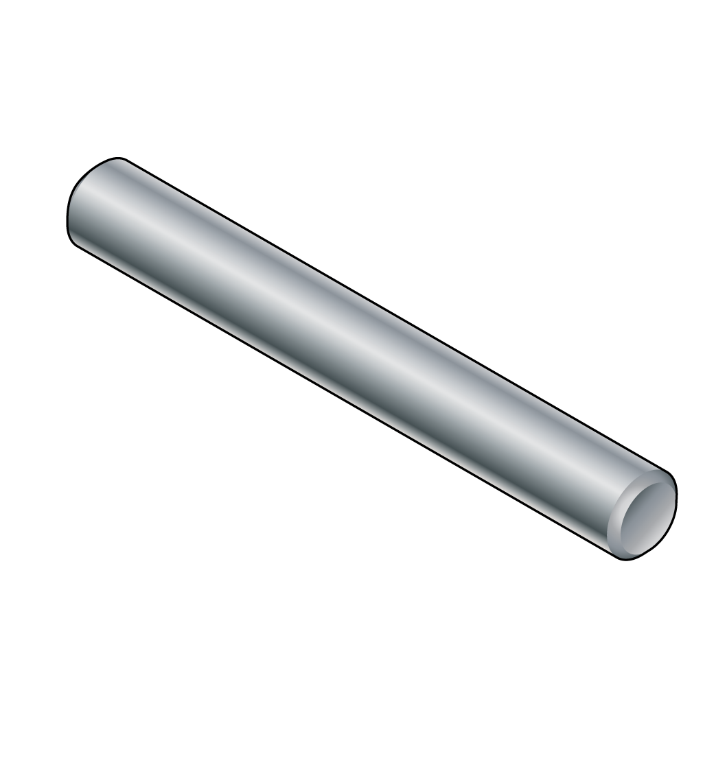 Dowels
 GLT
GLT Tornillos