
Ribbed Deck Design Software for AS1720.1 | Engineering Platform
Launch the free Ribbed Deck Calculator below & verify your design in seconds!
The New Standard for Australian Mass Timber Engineering
Ribbed Deck design is gaining attention in Australia as engineers look for more material-efficient mass timber floor systems, yet the path to a compliant design remains complex. Despite their structural efficiency and growing use, ribbed or cassette-style timber decks are rarely covered in university engineering programs, leaving many practitioners without clear guidance on their structural behaviour and design methodology.
Designing ribbed decks under the primary Australian timber code, AS 1720.1 – Timber Structures, presents a particular challenge: the standard does not currently contain “Deemed-to-Satisfy” (DtS) provisions for ribbed mass timber floor systems. This often requires engineers to pursue a Performance Solution pathway, combining first-principles structural analysis with the requirements of AS 1720.1 to verify bending, shear, and serviceability performance.
The Australian Engineering Platform for Ribbed Deck Design
Our platform performs a check for Ribbed Deck design to AS1720. The calculation module include:

Actualizaciones de nuestros socios
La plataforma de más rápido crecimiento para la especificación de madera
Key Ribbed Deck Design Capabilities
Overview of Ribbed Deck Systems
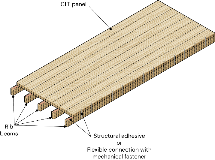
Ribbed deck systems are timber floor systems composed of a cross-laminated timber (CLT) slab connected to longitudinal rib beams. The ribs increase bending stiffness and load-bearing capacity while reducing material usage compared to solid CLT panels.
The SPEC Toolbox Ribbed Deck calculator allows engineers to analyze the structural behavior of ribbed timber floor systems under gravity loading. The calculator evaluates:
-
bending resistance
-
shear resistance
-
deflection performance
-
vibration behavior
-
connection capacity between slab and ribs
The system models the composite interaction between the CLT slab and rib beams using screw connections.
For the Australian region, the calculator supports the following timber design standards:
-
AS 1720:2010 – Timber Structures
-
NZS AS 1720:2022 – Timber Structures
-
EN 1995-1-1:2004 – Eurocode 5
The selected design standard determines the design parameters, safety factors, and verification procedures used in the analysis.
Ribbed Deck Configuration
A ribbed deck system consists of two main structural components:
-
CLT slab panels
-
Timber rib beams
The CLT slab distributes loads across the floor surface, while the ribs provide the primary bending resistance between supports.
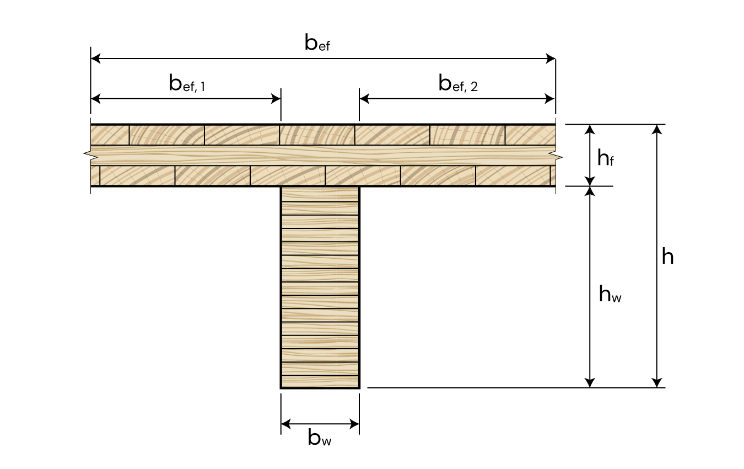
The system geometry is defined by:
-
CLT panel layup
-
rib beam dimensions
-
rib spacing
-
span length
-
connection type
These parameters determine the stiffness and load distribution of the floor system.
The ribbed deck configuration is defined using manual input. The available option is:
-
Custom Layup
This allows the user to fully define the CLT slab configuration and rib layout.
The CLT slab is defined using manual layer input, where the structural properties of each layer are specified. Input parameters include:
-
layer thickness
-
fiber orientation
-
timber grade
-
stacking configuration
This approach enables modeling of any CLT layup configuration, independent of manufacturer-specific products.
Rib beams act as the primary load-bearing elements of the ribbed deck system. Users define:
-
material type
-
supplier
-
timber grade
The rib geometry is defined using:
-
rib width (b)
-
rib depth (d)
-
rib spacing
These parameters control the bending stiffness and structural behavior of the ribbed deck.
The CLT slab and rib beams interact through mechanical fasteners. The calculator currently supports:
-
Flexible connection
This configuration models partial composite action between the slab and rib beams.
Structural Model
The ribbed deck is analyzed as a beam system subjected to distributed loads.
Users define:
-
span length
-
support conditions
-
load distribution
Loads are applied as uniformly distributed loads along the span.
The calculator can also include:
-
self-weight of structural elements
Topping
An additional topping layer may be applied above the CLT slab.
The topping load contributes to the permanent load acting on the floor system.
Vibration Methods
Floor vibration performance can be evaluated using the following methods:
-
Hamm et al. 2010
-
FPInnovations
-
prEN 1995:2023
Additional parameters include:
-
vibration performance level
-
damping ratio
-
walking frequency
-
support condition
-
floating screed stiffness
These parameters influence the dynamic response of the floor.

Screw Data
The connection between the CLT slab and rib beams is achieved using screws.
Users define:
-
fastener type (screw)
-
screw orientation (vertical)
-
member configuration (timber-to-timber or steel-to-timber)
-
thread type (partially or fully threaded)
Screw properties can be defined by selecting a manufacturer or by using manual input.
Available suppliers include:
-
Schmid
-
Eurotec
-
Klimas
-
Rothoblaas
-
Simpson Strong-Tie
-
Sihga
-
SPAX
-
Würth
-
Manual input
Connection geometry is defined using:
-
spacing along grain (a₁)
-
spacing across grain (a₂)
-
edge distance (a₃)
-
end distance (a₄)
-
embedment length
-
number of screws
These parameters determine the shear transfer capacity between the slab and ribs.
Analytical Methods
The ribbed deck analysis supports the following analytical methods:
-
Extended Gamma Method
-
Gamma Method
These methods calculate the effective bending stiffness of the composite ribbed deck system, considering the flexibility of the screw connection.
Design Checks
After analysis, the calculator provides a summary of structural performance.
The following checks are evaluated:
-
Desviación
-
Vibración
-
Shear
-
Bending
-
Connection Capacity
Each verification includes a utilization ratio and pass/fail indicator, allowing engineers to quickly evaluate the performance of the ribbed deck system.
Tutorials
CLT Floor-to-Wall Connection Design

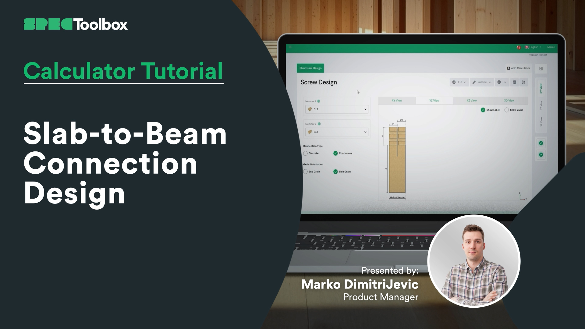
Slab-to-Beam Connection Design
Half-Lap Connection Design
Join us as we break down the Half-Lap joint design, focusing on maintaining structural continuity without external steel plates. Using the Screw Module, we walk through the auto-checking of edge distances and spacing requirements critical for these tight geometric joints.

Calculadora de paredes CLT
En este vídeo, aprenderás paso a paso cómo diseñar un elemento de pared CLT típico. Trataremos la selección de un proveedor de CLT, el uso de las funciones adecuadas, imágenes dinámicas y contenido educativo para determinar el grosor y el diseño óptimos del panel. También verás cómo cambiar entre los tipos de estructura Platform y Balloon, aplicar diferentes métodos de excentricidad y añadir cargas en el plano y fuera del plano, lo que te proporcionará una sólida comprensión de los fundamentos del cálculo y el diseño de paredes CLT.
La madera maciza está dando forma al futuro de la construcción sostenible. Con la aparición de edificios de madera que baten récords en todo el mundo, dominar el diseño de CLT es más relevante que nunca. Echa un vistazo a nuestra aplicación CLT Toolbox para acceder a potentes herramientas de diseño, cálculos automatizados y conocimientos de expertos que te ayudarán a optimizar tus proyectos de CLT.

Calculadora de diseño de diafragmas CLT
Una guía completa para configurar y analizar el comportamiento del diafragma en la dirección X utilizando CLT Toolbox. Definirá los tipos de tornillos para los cálculos de rigidez, establecerá la geometría del panel, los tipos de conexión y los anchos de los paneles. Cubrimos cómo introducir las fuerzas ULS y SLS, y explicamos los valores de corte en el plano y los datos de laminación necesarios. El vídeo termina con un desglose de los resultados de deflexión, las acciones de fuerza y las comprobaciones de resistencia según el Eurocódigo 5.

Diseño contra incendios para suelos CLT
Nos complace presentar el tan esperado módulo Fire Design para suelos CLT, ahora disponible junto con la calculadora de diseño ambiental en CLT Toolbox.
Este tutorial explica cómo funciona el nuevo módulo, incluyendo qué estándares son compatibles y cómo se calcula la profundidad de caracteres capa por capa.
Key features include:
- Support for multiple fire models:
– Draft Eurocode 5 (prEN 1995-1-2:2023)
– Austrian National Annex (ÖNORM B EN 1995-1-2:2011)
– Standard Fire Tests (ISO 834 / EN 1363-1) - Flexibility to define protection layers and fire-exposed sides
- Automatic layer-by-layer charring depth calculations over time
- Clear logic for bond-line failure and glue-line degradation
- Full PDF export with all intermediate steps, safety factors and inputs
Diseñado para proporcionar a los ingenieros transparencia, precisión y rapidez en el diseño contra incendios de CLT.

Diseño de muros de corte CLT
Nos complace anunciar que la segunda versión de nuestra calculadora de muros de corte CLT ya está disponible.
Tras 12 meses escuchando los comentarios de los usuarios, nos complace presentar una herramienta mejorada y más robusta para el diseño de muros de corte.
Los muros de corte CLT tienen una excelente resistencia en el plano y pueden servir como un sistema fiable de resistencia a las cargas laterales.
La segunda versión de la calculadora incluye características tales como cinco métodos de transferencia de carga de vanguardia, aprovechando las investigaciones de Casagrande, Wallner-Novak, Tomasi, Pei y Reynolds. También hemos añadido comprobaciones de deformación lateral y cálculos de rigidez de paneles siguiendo la guía ProHolz 2014. Por último, también incluimos el diseño en plano de CLT según Proholz 2014 y FP Innovations 2019.
Durante el mes de octubre, la calculadora de muros de corte estará disponible en la versión gratuita. Así que entra en la aplicación y échale un vistazo 🙂.

Calculadora de diseño de suelos CLT
Acompáñenos mientras exploramos todo lo necesario, desde la elección del panel CLT ideal —ya sea que opte por el producto de un proveedor o introduzca manualmente sus propios datos— hasta la selección del anexo nacional adecuado, la definición de las cargas y el perfeccionamiento de los detalles más precisos. Este vídeo le guiará a través de cada etapa, incluyendo el análisis estructural, los cálculos de rigidez e incluso la integración de láminas encoladas en los bordes en su diseño.
También examinaremos cómo afectan a su estructura diversas técnicas de vibración y le revelaremos cómo puede optimizar su diseño teniendo en cuenta la rigidez en el plano de la solera de hormigón y la influencia del soporte flexible. Además, podrá realizar un seguimiento de los resultados y las fórmulas a lo largo de todo el proceso, lo que le garantizará estar siempre al tanto de todo.
¡Empecemos!

Calculadora de diseño de diafragmas CLT
Comience con un enfoque integral para el diseño de diafragmas definiendo las fuerzas, las propiedades de los materiales y aplicando los parámetros del Eurocódigo 5. Empiece por definir las fuerzas de entrada que actúan sobre el diafragma en la dirección X y seleccione los tipos de tornillos para los cálculos de rigidez. Establezca la geometría y la orientación del diafragma en las entradas del usuario, el tipo de conexiones de los paneles y el ancho de los paneles con la información técnica de los proveedores de CLT. Introduzca las fuerzas tanto para ULS como para SLS, teniendo en cuenta la dirección de la fuerza. Comprenda los valores de corte en el plano, los datos de laminación necesarios y los parámetros de diseño clave para el Eurocódigo 5. Por último, analice los resultados de la deflexión, la teoría subyacente, las fuerzas de acción y las comprobaciones de resistencia para garantizar un diseño preciso y eficiente.

Frequently Asked Questions
What structural advantages do ribbed timber decks provide?
Ribbed decks increase structural efficiency by separating the bending elements (ribs) from the load distribution layer (CLT slab). This configuration increases bending stiffness while reducing material usage and overall floor weight compared to solid timber panels.
How is the interaction between the CLT slab and ribs modeled?
The CLT slab and rib beams are connected using mechanical fasteners, typically screws. In the calculator this connection is modeled as a flexible connection, allowing partial composite action between the slab and ribs.

 Dowels
 CLT
CLT Tornillos
 GLT
GLT Soportes
 Light-frame
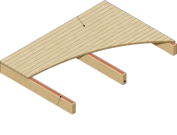 Cubierta acanalada
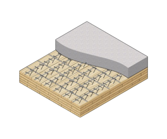 TCC
TCC